Intermatic EK4436SM Bedienungsanleitung
Intermatic Nicht kategorisiert EK4436SM
Lies die bedienungsanleitung für Intermatic EK4436SM (2 Seiten) kostenlos online; sie gehört zur Kategorie Nicht kategorisiert. Dieses Handbuch wurde von 7 Personen als hilfreich bewertet und erhielt im Schnitt 4.2 Sterne aus 3 Bewertungen. Hast du eine Frage zu Intermatic EK4436SM oder möchtest du andere Nutzer dieses Produkts befragen? Stelle eine Frage
Seite 1/2
• Disconnect power at the circuit breaker(s) or disconnect switch(es) before beginning installation or servicing.
• Do NOT use the OFF state of the photocontrol for equipment servicing.
Risk of Fire or Electric Shock
PHOTOCONTROL
PHOTOCONTROLE
FOTOCONTROL
Installation and Setup Instructions
MODEL K4000, ELC4000, EK4000 Series
MODÈLE SérieK4000, ELC4000, EK4000
MODELO serie K4000, ELC4000, EK4000
NO
NO
NO
NOTICE
TICE
TICE
TICENOTICE
• DO NOT MOUNT WITH THE WIRES FACING UP.
Installation:
Mounting Options/ Options de montage/ Opciones de montaje
Accessories/ Accessoires/ Accesorios
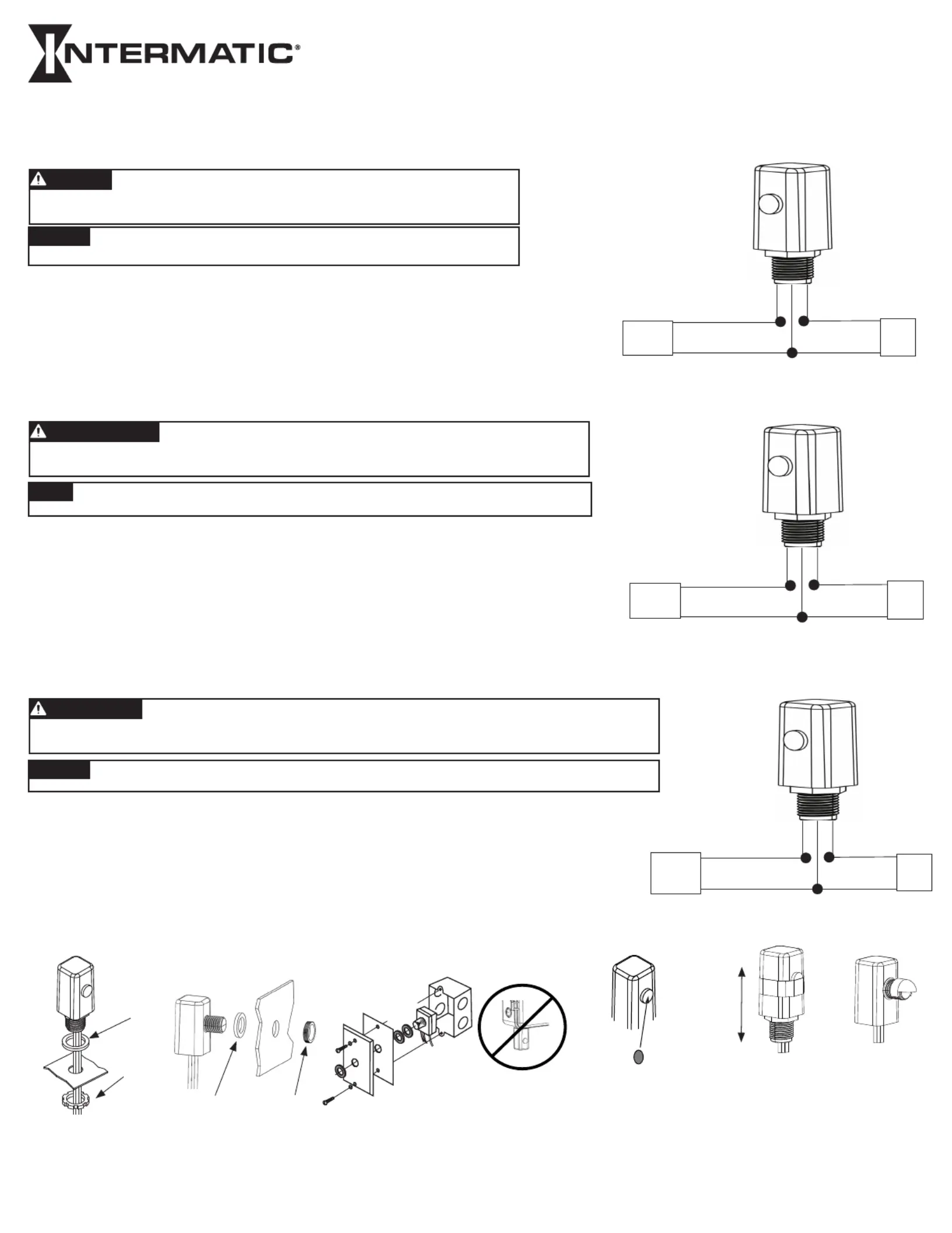
Line 1 - Input
Load 1 - Output
Neutral
(if 120/277/347 Vac)
Line 2
(if 208/240/480 Vac)
or
Load 2/Neutral
Black
White
Red
From Breaker
or
Power Source
To Lights
or Load
NUT
ÉCROU
TUERCA
GASKET
JOINT
JUNTA
GASKET
JOINT
JUNTA
NUT
ÉCROU
TUERCA
WARNING
1. Make sure to turn the power off at the breaker before installation.
2. Mount with an approved outdoor junction box or fixture using the included gasket and nut. (See photo)
DO NOT MOUNT WITH THE WIRES FACING UP OR ON THE BOTTOM OF AN ENCLOSURE.
3. Orient the lens of the photocontrol so it faces NORTH and away from artificial light sources that may cause the load to
turn off at night.
4. See diagram for wiring.
5. When all wiring is complete, you can turn the breaker back on to restore power to the photocontrol.
6. Test the unit by covering the lens of the photocontrol with a leather glove or similar. The photocontrol should react to a change within
60 seconds.
Accessories: Use when there is a high amount of incident light on the photocontrol from artificial light sources that may interfere with proper operation of photocontrol.
Accessoires: À utiliser si la commande photo-électronique est exposée à une grande quantité de lumière incidente provenant de sources de lumière artificielle susceptibles de nuire à son bon fonctionnement.
Accesorios: Se debe usar donde hay una gran cantidad de luz incidente en el control fotoelectrónico proveniente de fuentes de luz artificiales que puedan interferir con el funcionamiento correcto del control
fotoelectrónico.
Instructions d’installation et de configuration
Ratings:
Refer to product unit label for load rating information
Notes :
Reportez-vous à l’étiquette de l’unité du produit pour obtenir des informations sur la capacité de charge.
• Desconecte la alimentación eléctrica de los disyuntores o desconecte los interruptores antes de comenzar la instalación o el mantenimiento.
• NO use el estado OFF (apagado) del control fotoelectrónico para realizar mantenimiento del equipo.
Riesgo de incendio o descarga eléctrica
AVISO
AVISO
AVISO
AVISOAVISO
• NO LO MONTE CON LOS CABLES HACIA ARRIBA.
Instalación:
ADVERTENCIA
1. Asegúrese de desconectar la alimentación eléctrica en el disyuntor antes de la instalación.
2. Monte con una caja de conexiones o luminaria aprobada para exteriores con la junta y la tuerca incluidas. (Ver foto)
NO MONTE CON LOS CABLES HACIA ARRIBA O EN LA PARTE INFERIOR DE UN RECINTO.
3. Oriente la lente del control fotoelectrónico de forma que apunte al NORTE y lejos de fuentes de luz artificiales que puedan provocar que la
carga se apague por la noche.
4. Consulte el diagrama a continuación para ver el cableado.
5. Cuando todo el cableado esté completo, puede volver a activar el disyuntor para restablecer la alimentación eléctrica del
control fotoelectrónico.
6. Para probar la unidad, cubra la lente del control fotoelectrónico con un guante de cuero o similar. El control fotoelectrónico debe reaccionar al
cambio en el transcurso de 60 segundos.
Calificaciones:
Consulte la etiqueta de la unidad del producto para obtener información sobre la capacidad de carga.
Línea 1 - Entrada
Carga 1 - Salida
Neutro
(si 120/277/347 V CA)
Línea 2
(si 208/240/480 V CA)
o
Carga 2/Neutro
Negro
Blanco
Rojo
Desde el
disyuntor o
fuente de
alimentación
A luces
o carga
LIGHT SHIELD LABEL (LGLBL)
ÉTIQUETTE PARE-LUMIÈRE
(LGLBL)
ETIQUETA DE PANTALLA
DE LUZ (LGLBL)
LIGHT SHIELD
BRACKET (22LG0120)
SUPPORT PARE-
LUMIÈRE (22LG0120)
SOPORTE DE
PANTALLA DE LUZ
(22LG0120)
LIGHT SHIELD
DOME (6LV1352)
DÔME PARE-
LUMIÈRE
(6LV1352)
DOMO DE
PANTALLA DE LUZ
(6LV1352)
Instalación e instrucciones de configuración
Ligne 1 - Entrée
Charge 1 - Sortie
Neutre
(si 120/277/347 VCA)
Ligne 2
(si 208/240/480 VCA)
ou
Charge 2/Neutre
Noir
Blanc
Rouge
Du disjoncteur
ou de la source
d'alimentation
Vers les
lumières
ou la
charge
• Débrancher l’alimentation au niveau des disjoncteurs ou des sectionneurs avant de procéder à l’installation ou à l’entretien.
• Ne PAS utiliser l’état ARRÊT de la commande photo-électronique pour travailler sur le matériel.
Risque d’incendie ou d’électrocution
AVIS
AVIS
AVIS
AVISAVIS
• NE PAS MONTER AVEC LES FILS VERS LE HAUT.
Installation:
AVERTISSEMENT
1. Veiller à couper l’alimentation au niveau du disjoncteur avant de procéder à l’installation.
2. Effectuer le montage à l’aide d’une boîte de dérivation ou un luminaire homologués pour l’extérieur à l’aide du joint et de l’écrou
fournis (Voir photo)
NE PAS MONTER AVEC LES FILS ORIENTÉS VERS LE HAUT OU VERS LE BAS D’UN BOÎTIER.
3. Orienter la lentille de la commande photo-électronique de sorte qu’elle soit orientée vers le NORD et à l’écart de sources de lumière
artificielle susceptibles de provoquer l’ouverture du circuit de charge la nuit.
4. Voir le schéma de câblage.
5. Une fois le câblage terminé, il sera possible de remettre le disjoncteur en marche pour rétablir l’alimentation dans la commande
photo-électronique.
6. Pour vérifier le fonctionnement, couvrir la lentille de la commande photo-électronique avec un gant de cuir ou un produit similaire. La
commande photo-électronique doit réagir à ce changement au bout de 60secondes.
Produktspezifikationen
| Marke: | Intermatic |
| Kategorie: | Nicht kategorisiert |
| Modell: | EK4436SM |
Brauchst du Hilfe?
Wenn Sie Hilfe mit Intermatic EK4436SM benötigen, stellen Sie unten eine Frage und andere Benutzer werden Ihnen antworten
Bedienungsanleitung Nicht kategorisiert Intermatic

5 November 2025
5 November 2025
4 September 2025
3 September 2025
20 August 2025
20 August 2025
4 August 2025
2 August 2025
2 August 2025
2 August 2025
Bedienungsanleitung Nicht kategorisiert
Neueste Bedienungsanleitung für -Kategorien-
3 April 2026
3 April 2026
3 April 2026
3 April 2026
3 April 2026
3 April 2026
3 April 2026
3 April 2026
3 April 2026
3 April 2026