Intermatic ETCB28458PCR Bedienungsanleitung
Intermatic Nicht kategorisiert ETCB28458PCR
Lies die bedienungsanleitung für Intermatic ETCB28458PCR (12 Seiten) kostenlos online; sie gehört zur Kategorie Nicht kategorisiert. Dieses Handbuch wurde von 4 Personen als hilfreich bewertet und erhielt im Schnitt 4.4 Sterne aus 7 Bewertungen. Hast du eine Frage zu Intermatic ETCB28458PCR oder möchtest du andere Nutzer dieses Produkts befragen? Stelle eine Frage
Seite 1/12
8-Pole Lighting Contractor Box
Installation and Setup Instructions
With 100-Hour Backup
Federal Communications Commission (FCC) Notice for ETCB28458PCR Time Switch
Description
This document explains the setup and conguration of the Intermatic
ETCB28458PCR 4-Pole Lighting Contractor Box with an Indoor/Outdoor Type 3
enclosure. The ETCB28458PCR’s built-in time switch automatically switches
loads according to the entered weekly schedule, holiday schedule, or from a
remote override. The time switch can support up to 48 xed ON and 48 xed
OFF events (96 total), up to 4 Astro events, and 50 holiday events. Each xed
event can be applied to any combination of days.
Contractor box features a built-in time switch, a 4-Pole contactor, a remote
input for a photocontrol, an input location for a surge device, as well as an input
for a standard switch to be used. The built-in time clock features an LCD and
panel-mounted control buttons to set, review, and monitor the time switch
functions, including setting date and time, schedule creation, enabling or
disabling Daylight Saving Time (DST) and conguring DST switchover dates.
Follow these instructions to complete the installation and programming of the
ETCB28458PCR 4-Pole Lighting Contractor Box.
This device complies with part 15 of the FCC rules. Operation of this device is subject to the following two conditions: (1) This device
may not cause harmful interference, and (2) This device must accept any interference, including interference that may cause
undesired operation. This equipment has been tested and found to comply with the limits for a Class A digital device, pursuant to
Part 15 of the FCC Rules. These limits are designed to provide reasonable protection against harmful interference when the
equipment is operated in a commercial environment. This equipment generates, uses and radiates radio frequency energy and, if
not installed and used in accordance with instructions, may cause harmful interference to radio communications. Operation of this
equipment in a residential area is likely to cause harmful interference that requires the user to correct at his or her own expense.
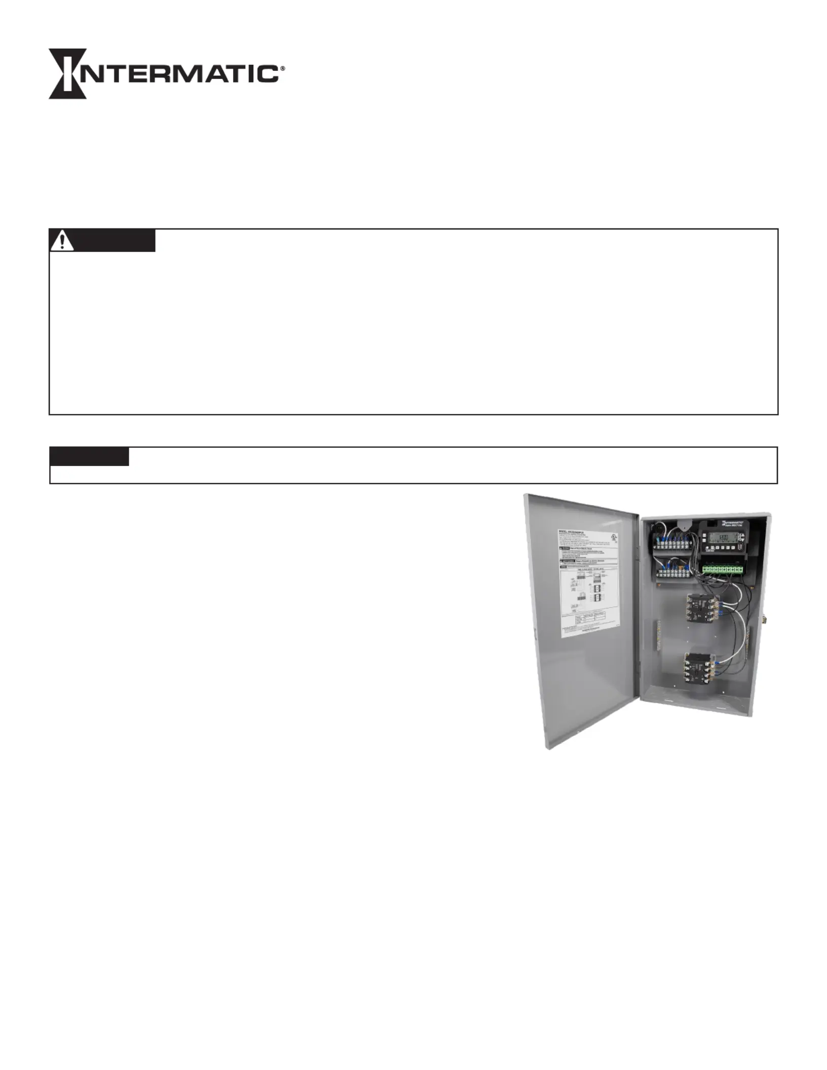
MODEL ETCB28458PCR
Shown in indoor/outdoor
lockable metal enclosure with
deadfront cover removed
NOTICE
• Do NOT touch circuit board components, contact can create a static discharge, which can damage these electronic components.
• Disconnect power at the circuit breaker(s) or disconnect switch(es) before installing or servicing.
• More than one circuit breaker or disconnect switch may be required to de-energize the equipment before servicing.
• For plastic enclosures, bonding between conduit connections is not automatic and must be provided as part of the installation.
• Installation and/or wiring must be in accordance with National and Local Electrical Code requirements.
• Load Voltage lead sizes #14 - #4 AWG, rated at least 105°C - USE COPPER CONDUCTORS ONLY.
• If the power disconnect point is out of sight, lock it in the OFF position and tag it to prevent unexpected application power.
• Make sure there is no wire insulation under the terminal plate on the time switch connector. Firmly tighten terminal screws.
• For outdoor locations or wet locations (rain-tight), conduit hubs that comply with requirements of the UL514B (standard for fitting conduit and
outlet boxes) are to be used.
• Do NOT exceed maximum current carrying capacity.
• Dead front must be secured in place when not servicing.
• KEEP DOOR CLOSED AT ALL TIMES when not servicing.
Risk of Fire or Electric Shock
WARNING
1
Produktspezifikationen
| Marke: | Intermatic |
| Kategorie: | Nicht kategorisiert |
| Modell: | ETCB28458PCR |
Brauchst du Hilfe?
Wenn Sie Hilfe mit Intermatic ETCB28458PCR benötigen, stellen Sie unten eine Frage und andere Benutzer werden Ihnen antworten
Bedienungsanleitung Nicht kategorisiert Intermatic

5 November 2025
5 November 2025
4 September 2025
3 September 2025
20 August 2025
20 August 2025
4 August 2025
2 August 2025
2 August 2025
2 August 2025
Bedienungsanleitung Nicht kategorisiert
Neueste Bedienungsanleitung für -Kategorien-
3 April 2026
3 April 2026
3 April 2026
3 April 2026
3 April 2026
3 April 2026
3 April 2026
3 April 2026
3 April 2026
3 April 2026