Intermatic T104-50 Bedienungsanleitung
Intermatic Schalter T104-50
Lies die bedienungsanleitung für Intermatic T104-50 (24 Seiten) kostenlos online; sie gehört zur Kategorie Schalter. Dieses Handbuch wurde von 7 Personen als hilfreich bewertet und erhielt im Schnitt 4.6 Sterne aus 9 Bewertungen. Hast du eine Frage zu Intermatic T104-50 oder möchtest du andere Nutzer dieses Produkts befragen? Stelle eine Frage
Seite 1/24
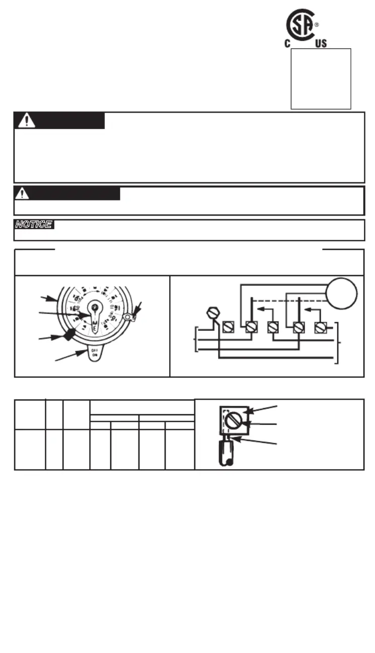
PRESSURE PLATE
TERMINAL SCREW
MAKE SURE WIRE
INSULATION CLEARS
PRESSURE PLATE
MINIMUM
COPPER
WIRE SIZE
(AWG)
MAX.
LOAD
(AMP)
MIN.
INSUL-
ATION
TEMP(°C)
75°C INSULATION MAX. MOTOR
LOAD (HP)
SINGLE PHASE
3 PHASE
120 V.240 V.208 V.
240 V.
14
12
10
8
15
20
30
40
90
90
90
90
1/2
1
2
-
2
2 1/2
3
5
N/A
N/A
TIME
POINTER
TIME
DIAL
OFF
TRIPPER
MANUAL
LEVER
ON
TRIPPER
CLOCK MOTOR: 208-277 VAC, 50 HZ.
CLOCK MOTOR VOLTAGE AND CYCLE MUST BE AS SPECIFIED. TO
ORDER REPLACEMENT, INDICATE PART NO. (WG--) ON MOTOR COVER.
CLOCK
MOTOR
GROUND
A
1
2
3
4
GR
240V
SUPPLY
TO
LOAD(S)
LINE 1
LINE 2
277/480 VOLT CONNECT MOTOR LEADS TO TERMINALS
“A” AND 1 AND SUPPLY NEUTRAL TO TERMINAL “A”.
WIRING
DIAGRAM
240 V 2 WIRE
AND GROUND
LR3730
154--02044
UL
HOLOGRAM
LABEL
WARNING
Risk of Fire or Electric Shock
• Disconnect power at the circuit breaker(s) or disconnect switch(es) before installing or servicing.
• Installation and/or wiring must be in accordance with national and local electrical code requirements.
• Use wires rated at least 90°C - COPPER conductors ONLY.
• Replace plastic insulator covering terminals before powering ON.
• KEEP DOOR CLOSED AT ALL TIMES when not servicing.
NOTICE
• Rotate timer dial clockwise only.
• Do not move the clock hands on the timer. Moving the clock hands can damage the timer.
AVERTISSEMENT
Risque d’incendie ou de choc électrique
• Utiliser des fils classés 90°C minimum - Conducteurs en CUIVRE UNIQUEMENT.
PROGRAMMING INSTRUCTIONS
1. TO SET “ON” AND “OFF” TIMES: Hold trippers against edge of CLOCK-
DIALONOFF, pointing to time (AM or PM) when and operations are desired,
tighten tripper screws firmly. For additional tripper pairs on CLOCK-DIAL
order 156T1978A.
2. TO SET TIME-OF-DAY:Pull CLOCK-DIALoutward. Turn in either direction
and align the exact time-of-day on the (the time now, when CLOCK-DIAL
switch is being put into operation) to the pointer. DO NOT MOVE POINTER.
OPERATING INSTRUCTIONS
•
TO OPERATE SWITCH MANUALLY: MANUAL LEVERMove
CLOCK-below
DIAL left or right as indicated by arrows. This will not effect next operation.
• IN CASE OF POWER FAILURE,reset CLOCK-DIALto proper time-of-day.
See programming instructions.
INTERMATIC INCORPORATED
SPRING GROVE, ILLINOIS 60081-9698
MODEL: T104-50
24 HOUR DIAL TIME SWITCH
TYPE 1 INDOOR USE ONLY
DOUBLE POLE SINGLE THROW (DPST)
40 A RESISTIVE EACH POLE, 120-480 VAC
40 A INDUCTIVE, TUNGSTEN OR 1000 VA
PILOT DUTY EACH POLE 120V-277 VAC;
2 HP (24 FLA) - 120 VAC; 5 HP (28 FLA) - 240 VAC
16 A ELECTRONIC BALLAST, 277 VAC
WIRING INSTRUCTIONS: Remove 1/2 inch of insulation from wire ends. Tighten terminal screws firmly
(2-18 in-lbs). Use solid or stranded COPPER only. May use two wires of the same size and type.conductors
Produktspezifikationen
| Marke: | Intermatic |
| Kategorie: | Schalter |
| Modell: | T104-50 |
Brauchst du Hilfe?
Wenn Sie Hilfe mit Intermatic T104-50 benötigen, stellen Sie unten eine Frage und andere Benutzer werden Ihnen antworten
Bedienungsanleitung Schalter Intermatic

16 September 2025
30 Juli 2025
30 Juli 2025
30 Juli 2025
30 Juli 2025
30 Juli 2025
30 Juli 2025
27 Juli 2025
26 Juli 2025
26 Juli 2025
Bedienungsanleitung Schalter
Neueste Bedienungsanleitung für -Kategorien-
31 März 2026
30 März 2026
25 März 2026
22 März 2026
22 März 2026
21 März 2026
20 März 2026
20 März 2026
19 März 2026
19 März 2026