JobSite IR-E1HO Bedienungsanleitung
Lies die bedienungsanleitung für JobSite IR-E1HO (2 Seiten) kostenlos online; sie gehört zur Kategorie Empfänger. Dieses Handbuch wurde von 27 Personen als hilfreich bewertet und erhielt im Schnitt 4.7 Sterne aus 9 Bewertungen. Hast du eine Frage zu JobSite IR-E1HO oder möchtest du andere Nutzer dieses Produkts befragen? Stelle eine Frage
Seite 1/2
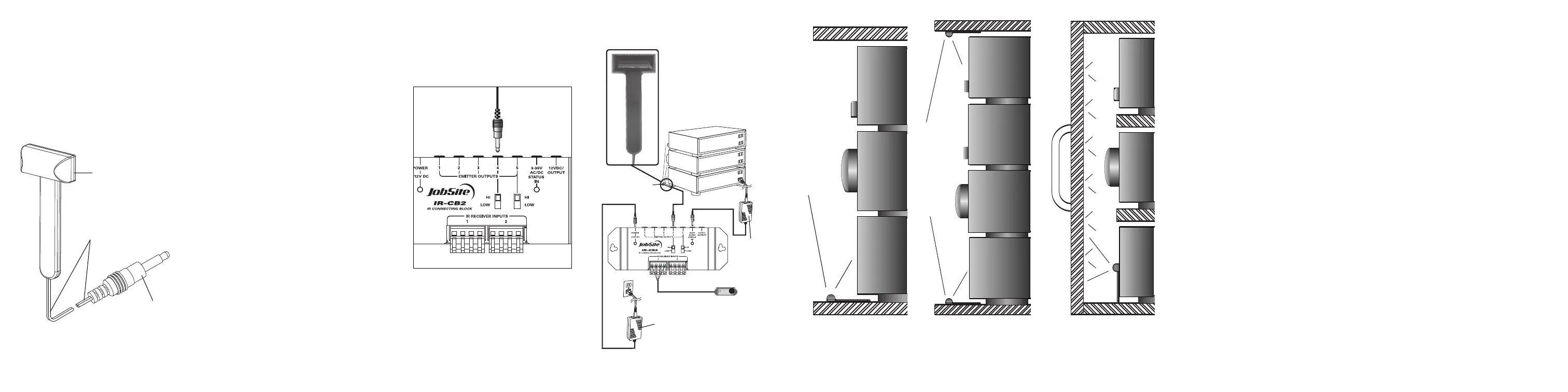
FIGURE 2IR-E1HO placed at the
bottom of the cabinet controlling a
stack of components .
FIGURE 3IR-E1HOplaced at the
bottom and the top of the cabinet
controlling a tall stack of components.
FIGURE 4IR-E1HO placed facing the
cabinet door controlling a stack of
components by reflecting infrared
commands.
FEATURES
nHigh output for controlling an entire stack of
A/V system
Installation friendly design:
n10' of cable with 3.5mm plug
nReliable adhesive backing
PRODUCT OVERVIEW
145236
(Over Please)
PACKAGE CONTENTS:
nIR-E1HO Emitter x 1
n10 Feet of connecting wire x 1
PREPARING FOR INSTALLATION
The IR-E1HO is typically used as a “flooding”
emitter to control a stack of audio/video
components. For this type of application, place the
IR-E1HO with its LEDs pointed straight up and at
least an inch in front of the equipment you wish to
control. For tall stacks of components use multiple
IR-E1HO emitters. Make sure the mounting surface
is cleaned and degreased before installation.
INSTALLATION
1. Test the operation of the IR-E1HO in the planned
mounting location. If all of the components
operate correctly via the IR repeater system,
proceed.
2. Make sure the mounting surface is clean.
3. Remove the protective coating from the self-
adhesive tape and attach the IR-E1HO to the
mounting surface.
4. Route the connecting two-conductor wire to the
IR Connecting Block and plug it into an emitter
output.
FIGURE 1Connecting the emitter to the main system
unit’s emitter low outputs.
5. Coil any excess wire and tie it in place.
6. On IR Connecting Blocks with selectable emitter
outputs make certain the HI-LOW SWITCH is
placed in the HI position. See figure 1
Double
sided tape
10feetof
2-conductor
22gauge
connectingwire
3.5mm Plug
Increasing the Wire Length
If the connecting wire is too short to reach the IR
Connecting Blocks, an additional length of wire
may be spliced in to extend it. Cut the emitter wire
approximately six inches from the plug end, strip
off 1/4", and connect your additional wiring
between the ends of the original emitter wire. For
distances between 10 and 20 feet upgrade the
original wire to an 18 gauge 2-conductor wire. For
distances of up to 200 feet a 16 gauge two-
conductor wire should be used. Be sure to
observe proper polarity when extending the
emitter wire.
The wire lead marked with a gray stripe is positive
(+); the unmarked lead is negative (-).
Mounting the IR-E1HO
Test the operation of the IR-E1HO in the planned
mounting location. If all of the components operate
correctly via the IR Repeater system, mount the IR-
E1HO using its self-adhesive strip. Make sure the
mounting surface is clean and dry. Remove the
protective coating from the back of the strip
attached to the IR-E1HO and stick it in place. Coil
any excess connecting wire and tie it in place.
TROUBLESHOOTING
Testing the Remote Control
Test that the hand-held remote control operates
the component when you point it at the front panel
(check the batteries if it does not).
IR Connecting
Block Power Supply
Check that the red power light on the IR
Connecting Block is lit (the in-line power supply
should be plugged into an active AC wall outlet
and supplying 12V DC).
IR Saturation
Sometimes a high output emitter can saturate the
IR receiving window of a component. When this
occurs, the IR command will not be executed.
This can occur on an intermittent basis when
there is a Plasma TV in the system.
Solution:
1. Turn off the Plasma TV, because this may be
contributing to the problem.
2. Replace the IR-E1HO Emitter with IR-E1 and
IR-E2 Emitters
3. Relocate the IR Emitter approximately 1/2"
away from the IR Receiving window of the
component, which isn’t responding to IR
commands. Some experimentation will be
required to determine the best location
for emitter.
4. Test system. Do not use an IR Blocking Cover if
the component is sensitive to IR saturation.
78
INSTALLATION DIAGRAM
12V DC
Power Supply
(Not Supplied)
plugged into
the Switched
Outlet
12V DC Power Supply
Plugged into an Unswitched
AC Outlet Powers the
System
IR-CB2
JobSite
IR-E1HO
Emitter
IR-E1HO
IR-SMR
Stereo
Receiver
CD
DSS
Produktspezifikationen
| Marke: | JobSite |
| Kategorie: | Empfänger |
| Modell: | IR-E1HO |
Brauchst du Hilfe?
Wenn Sie Hilfe mit JobSite IR-E1HO benötigen, stellen Sie unten eine Frage und andere Benutzer werden Ihnen antworten
Bedienungsanleitung Empfänger JobSite

2 September 2025
Bedienungsanleitung Empfänger
Neueste Bedienungsanleitung für -Kategorien-
1 April 2026
31 März 2026
30 März 2026
30 März 2026
30 März 2026
30 März 2026
30 März 2026
29 März 2026
29 März 2026
28 März 2026