JUNG 4008 TSM Bedienungsanleitung
JUNG Nicht kategorisiert 4008 TSM
Lies die bedienungsanleitung für JUNG 4008 TSM (8 Seiten) kostenlos online; sie gehört zur Kategorie Nicht kategorisiert. Dieses Handbuch wurde von 25 Personen als hilfreich bewertet und erhielt im Schnitt 4.6 Sterne aus 3 Bewertungen. Hast du eine Frage zu JUNG 4008 TSM oder möchtest du andere Nutzer dieses Produkts befragen? Stelle eine Frage
Seite 1/8
Page 1
0024015020 12.10.2012
Push-button sensor module
Ref.-no.: 4008 TSM
Safety instructions
Caution! Electrical devices may only be installed and tted by electrically skilled persons.
Non-compliance with the installation information could cause damage to the device, re or other hazards.
Connect the push-button sensor module exclusively to the universal relay or dimming station (no mains potential!).
To fasten radio to the supporting ring, only use the enclosed plastic screws.
These instructions are a component part of the product and must remain with the end customer.
Correct use
• Operation of consumers, e.g. light on/off, dimming, blinds/shutters up/down, calling up and saving light scenes etc.
• Connection to relay station or dimming station
• Installation in appliance box according to DIN 49073
Product characteristics
• 8 channels of the relay and dimming station can be controlled: switching, contact, dimming, blind/shutter.
• 16 channels for stations connected in parallel in conjunction with the push-button sensor expansion module.
• All channels of the stations can be connected in the state as delivered.
• Central function: all selected channels of the stations are controlled centrally
• Light scenes: up to 4 light scenes can be freely congured.
• Buttons can be congured corresponding to the cover kit.
• Programming without additional aids
• Free assignment of the buttons to the channels
• Red LED as status indicator (can be switched off)
• Blue orientation light (can be switched off)
• Feedback of switching states on all connected push-button sensor modules and sensor modules
• Up to 4 push-button sensor modules with up to 4 push-button sensor expansion modules can be connected to a single relay station (appli-
cation e.g. in two-way circuits or cross connections)
• Cloning of push-button sensor modules: transmitting the button assignment of a push-button sensor module to other push-button sensor
modules (application e.g. in changeover or cross connections)
• Push-button sensor modules and push-button sensor modules with expansion module can be cloned
• Easy installation using 2-wire cable
• Covers can be labelled using the laser labelling tool on the Internet under www.jung-lasern.de
• Operation
• Each button can be operated over its entire surface or top/bottom, depending on the programming. The function depends on the setting of
the station.
• Switching / momentary contact: press button briey.
• Move blind/shutter: press and hold button.
• Stop or adjust blind/shutter: press button briey
• Dimming: press and hold button
Structure of the device
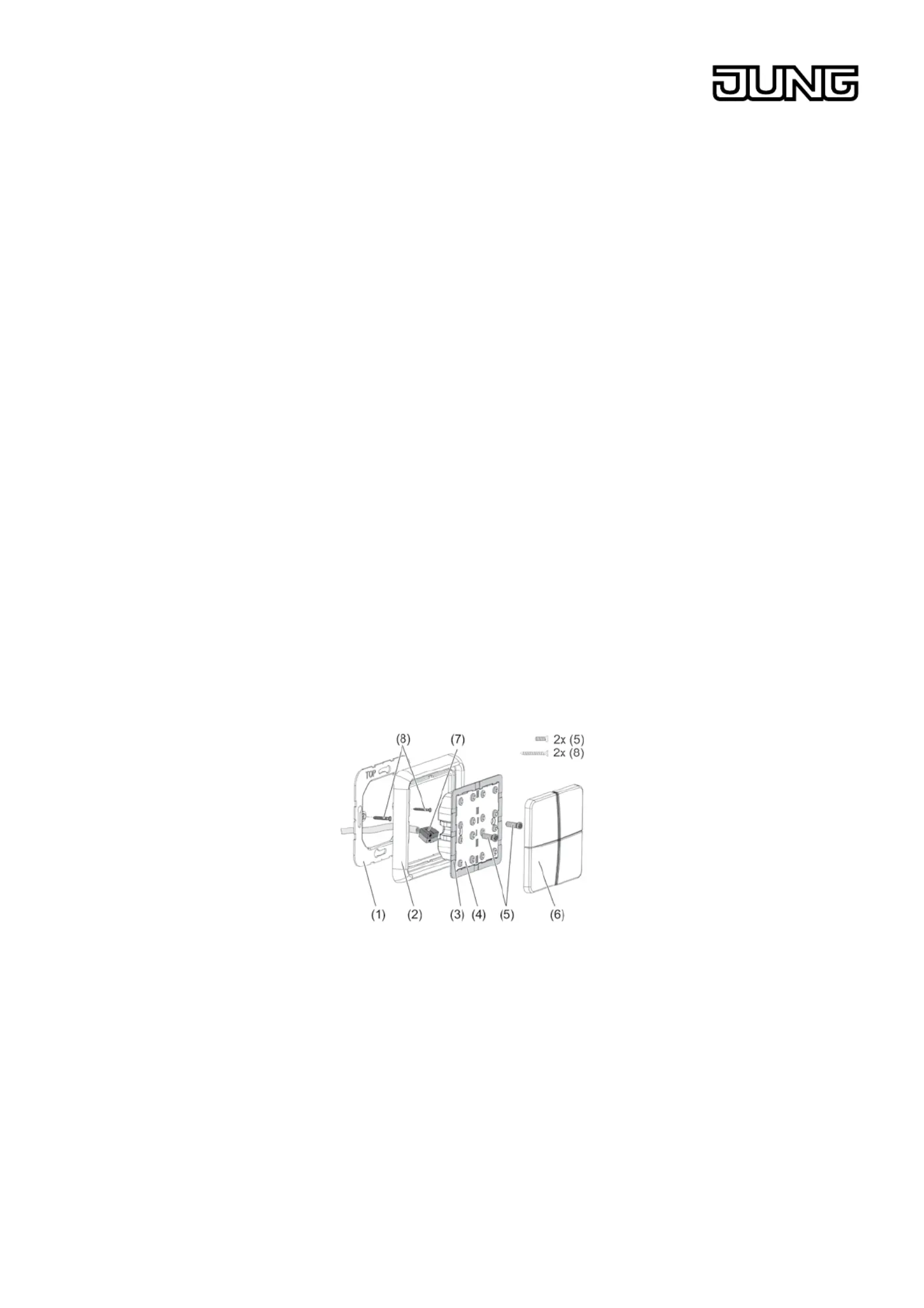
Bild 1: Installation
(1) Supporting ring
(2) Frame
(3) Adapter frame
(4) Push-button sensor module
(5) Locking screw
(6) Button set
(7) Connecting terminal
(8) Box screws
Produktspezifikationen
| Marke: | JUNG |
| Kategorie: | Nicht kategorisiert |
| Modell: | 4008 TSM |
Brauchst du Hilfe?
Wenn Sie Hilfe mit JUNG 4008 TSM benötigen, stellen Sie unten eine Frage und andere Benutzer werden Ihnen antworten
Bedienungsanleitung Nicht kategorisiert JUNG

11 August 2025
10 August 2025
1 August 2025
1 August 2025
1 August 2025
1 August 2025
1 August 2025
1 August 2025
26 Juli 2025
25 Juli 2025
Bedienungsanleitung Nicht kategorisiert
Neueste Bedienungsanleitung für -Kategorien-
14 Februar 2026
14 Februar 2026
14 Februar 2026
14 Februar 2026
14 Februar 2026
14 Februar 2026
14 Februar 2026
14 Februar 2026
14 Februar 2026
14 Februar 2026