JUNG BTS01 Bedienungsanleitung
Lies die bedienungsanleitung für JUNG BTS01 (3 Seiten) kostenlos online; sie gehört zur Kategorie Sensor. Dieses Handbuch wurde von 32 Personen als hilfreich bewertet und erhielt im Schnitt 4.4 Sterne aus 5 Bewertungen. Hast du eine Frage zu JUNG BTS01 oder möchtest du andere Nutzer dieses Produkts befragen? Stelle eine Frage
Seite 1/3
Condensation sensor
Condensation sensor
Condensation sensor
Condensation sensor
Condensation sensorCondensation sensor
Art. no.: BTS01
Operating instructions
Operating instructions
Operating instructions
Operating instructionsOperating instructions
1
1
1
11Safety instructions
Safety instructions
Safety instructions
Safety instructionsSafety instructions
Electrical devices may only be mounted and connected by electrically skilled persons.
Electrical devices may only be mounted and connected by electrically skilled persons.
Electrical devices may only be mounted and connected by electrically skilled persons.
Electrical devices may only be mounted and connected by electrically skilled persons.Electrical devices may only be mounted and connected by electrically skilled persons.
Serious injuries, fire or property damage possible. Please read and follow manual fully.
Serious injuries, fire or property damage possible. Please read and follow manual fully.
Serious injuries, fire or property damage possible. Please read and follow manual fully.
Serious injuries, fire or property damage possible. Please read and follow manual fully.Serious injuries, fire or property damage possible. Please read and follow manual fully.
Danger of electric shock. During installation and cable routing, comply with the regulations and
Danger of electric shock. During installation and cable routing, comply with the regulations and
Danger of electric shock. During installation and cable routing, comply with the regulations and
Danger of electric shock. During installation and cable routing, comply with the regulations andDanger of electric shock. During installation and cable routing, comply with the regulations and
standards which apply for SELV circuits.
standards which apply for SELV circuits.
standards which apply for SELV circuits.
standards which apply for SELV circuits.standards which apply for SELV circuits.
These instructions are an integral part of the product, and must remain with the end customer.
These instructions are an integral part of the product, and must remain with the end customer.
These instructions are an integral part of the product, and must remain with the end customer.
These instructions are an integral part of the product, and must remain with the end customer.These instructions are an integral part of the product, and must remain with the end customer.
2
2
2
22Device components
Device components
Device components
Device componentsDevice components
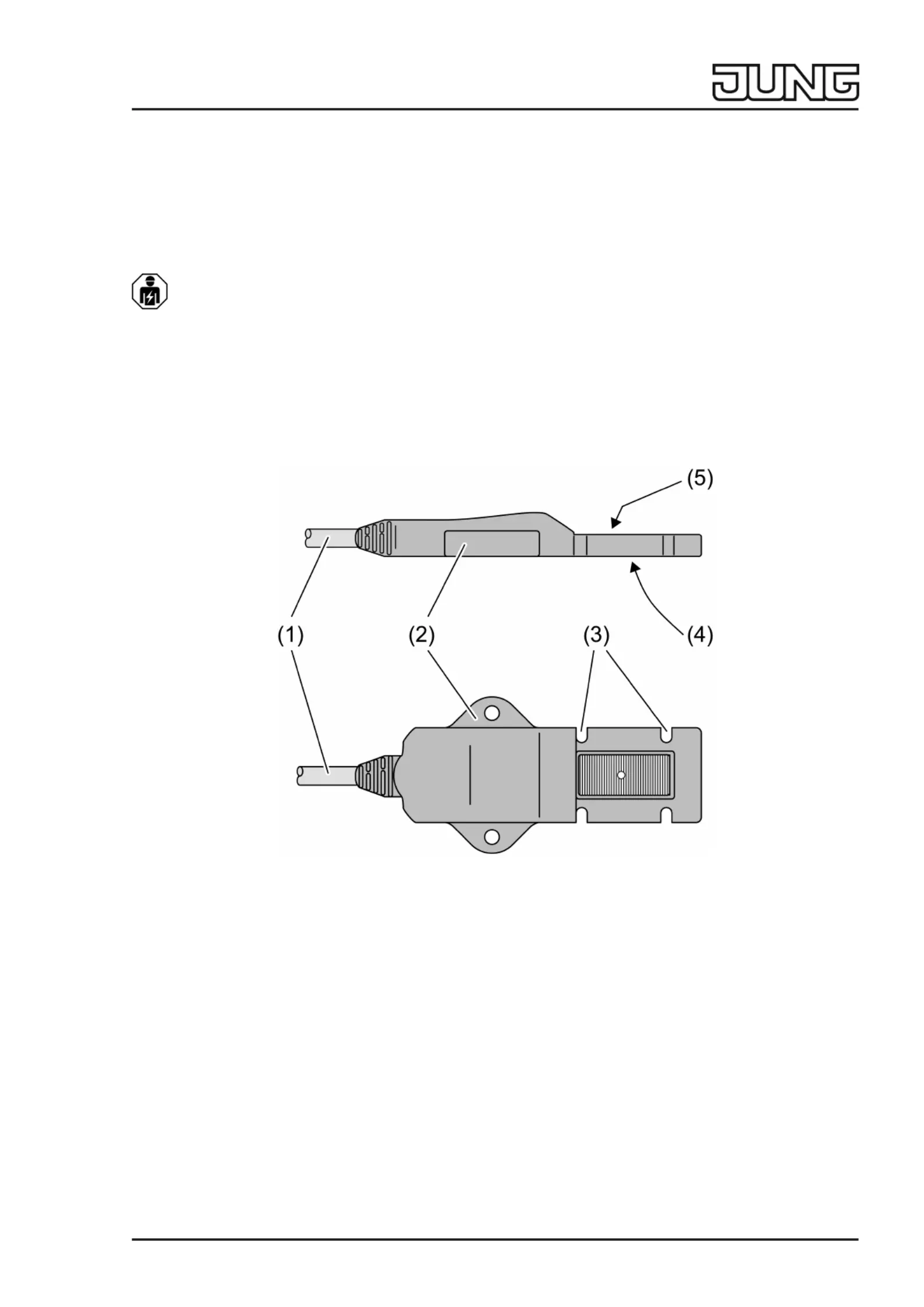
Figure1:
(1)Connecting cable
(2)Fixing strap
(3)Recession for fitting on ductwork with cable ties
(4)Recession for a thermally conducting pad
(5)Sensor surface
3
3
3
33Function
Function
Function
FunctionFunction
Intended use
Intended use
Intended use
Intended useIntended use
–Detection of water condensation on coolant lines in residential or functional buildings
–Connection to suitable binary inputs
–Fitting on the coolant line
Condensation sensor function
Condensation sensor function
Condensation sensor function
Condensation sensor functionCondensation sensor function
The device monitors the electrical conductivity between the conductive coatings on the sensor
surface. If it is dampened with water, the device detects the change and signals it.
1 / 3
8259593320.09.2021
j0082595933
Produktspezifikationen
| Marke: | JUNG |
| Kategorie: | Sensor |
| Modell: | BTS01 |
Brauchst du Hilfe?
Wenn Sie Hilfe mit JUNG BTS01 benötigen, stellen Sie unten eine Frage und andere Benutzer werden Ihnen antworten
Bedienungsanleitung Sensor JUNG

25 Juli 2025
14 Juli 2025
11 Juli 2025
11 Juli 2025
Bedienungsanleitung Sensor
Neueste Bedienungsanleitung für -Kategorien-
12 März 2026
12 Oktober 2025
12 Oktober 2025
12 Oktober 2025
12 Oktober 2025
12 Oktober 2025
12 Oktober 2025
12 Oktober 2025
12 Oktober 2025
12 Oktober 2025