JUNG SM1608 Bedienungsanleitung
JUNG Nicht kategorisiert SM1608
Lies die bedienungsanleitung für JUNG SM1608 (9 Seiten) kostenlos online; sie gehört zur Kategorie Nicht kategorisiert. Dieses Handbuch wurde von 7 Personen als hilfreich bewertet und erhielt im Schnitt 4.4 Sterne aus 5 Bewertungen. Hast du eine Frage zu JUNG SM1608 oder möchtest du andere Nutzer dieses Produkts befragen? Stelle eine Frage
Seite 1/9
Sensor module
Ref.No.: SM 1608
V03
Safety instructions
Caution! Electrical devices may only be installed and tted by electrically skilled persons.
Non-compliance with the installation information could cause damage to the device, re or other hazards.
Connect the module exclusively to the universal relay or dimming station (no mains potential!).
To fasten radio to the supporting ring, only use the enclosed plastic screws.
These instructions are a component part of the product and must remain with the end customer.
Function
Correct use
• Operation of consumers, e.g. light on/off, dimming, blinds/shutters up/down, calling up and saving light scenes etc.
• Connection to relay station or dimming station
• Installation in appliance box according to DIN 49073
Product characteristics
• Up to 16 load outputs of the relay or dimming station can be controlled.
• Switching, contact, dimming, blind/shutter
• Light scenes: up to 4 light scenes per control point can be freely congured.
• Central function: all assigned load outputs are switched on/off centrally.
• Free assignment of the sensor surfaces to the load outputs, central functions and light scenes
• Possible to change settings
• LED can be used as feedback and as orientation light
• Feedback of switching states on all connected sensor modules.
• LED brightness adjustable in 3 stages (100 %, 50 %, off).
• Up to 4 sensor modules can be connected to a single relay/dimming station, even with stations connected in paral-
lel.
• Cloning: transfer of a set assignment to another sensor module.
• If mains power fails, assignments are retained.
• Easy installation through 2-wire cable.
• Can be labelled using JUNG labelling tool.
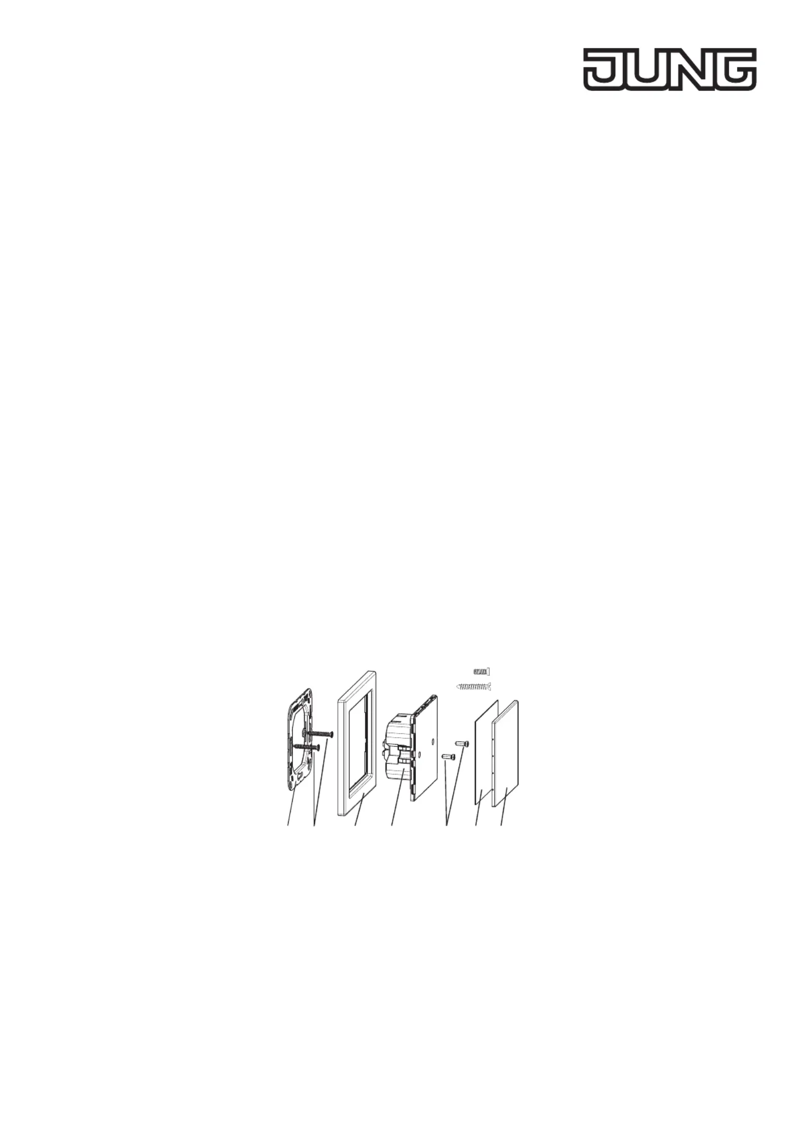
Structure of the device
2 x (5)
2 x (2)
(1)(2)(3)(4)(5)(6)(7)
Fig.1.: Structure of the device
(1) Supporting ring
(2) Box screws
(3) Frame
(4) Sensor module
(5) Plastic screws
(6) Insert for labelling
(7) Cover
Operation
Operation is through touching the respective sensor surface (button).
Operating blind/shutter
• Move blind/shutter: press and hold button
• Stop or adjust blind/shutter: press button briey
Produktspezifikationen
| Marke: | JUNG |
| Kategorie: | Nicht kategorisiert |
| Modell: | SM1608 |
Brauchst du Hilfe?
Wenn Sie Hilfe mit JUNG SM1608 benötigen, stellen Sie unten eine Frage und andere Benutzer werden Ihnen antworten
Bedienungsanleitung Nicht kategorisiert JUNG

11 August 2025
10 August 2025
1 August 2025
1 August 2025
1 August 2025
1 August 2025
1 August 2025
1 August 2025
26 Juli 2025
25 Juli 2025
Bedienungsanleitung Nicht kategorisiert
Neueste Bedienungsanleitung für -Kategorien-
1 April 2026
1 April 2026
1 April 2026
1 April 2026
1 April 2026
1 April 2026
1 April 2026
1 April 2026
1 April 2026
1 April 2026