Kenwood Excelon X803-5 Bedienungsanleitung
Lies die bedienungsanleitung für Kenwood Excelon X803-5 (11 Seiten) kostenlos online; sie gehört zur Kategorie Empfänger. Dieses Handbuch wurde von 3 Personen als hilfreich bewertet und erhielt im Schnitt 4.8 Sterne aus 2 Bewertungen. Hast du eine Frage zu Kenwood Excelon X803-5 oder möchtest du andere Nutzer dieses Produkts befragen? Stelle eine Frage
Seite 1/11

X803-5
KAC-835
CLASS D FIVE CHANNEL POWER AMPLIFIER
INSTRUCTION MANUAL
AMPLIFICATEUR DE PUISSANCE 5 CANAUX CLASSE D
MODE D’EMPLOI
AMPLIFICADOR DE POTENCIA DE 5 CANALES CLASE D
MANUAL DE INSTRUCCIONES
Take the time to read through this instruction manual.
Familiarity with installation and operation procedures will help you
obtain the best performance from your new power amplier.
For your records
Record the serial number, found on the back of the unit, in the spaces designated on the warranty card, and in the space provided below.
Refer to the model and serial numbers whenever you call upon your Kenwood dealer for information or service on the product.
Model X803-5 / KAC-835 Serial number
US Residence Only
Register Online
Register your Kenwood product at w ww.k
enwood.com/usa
B5A-4587-00 (K)
© 2024 JVCKENWOOD Corporation
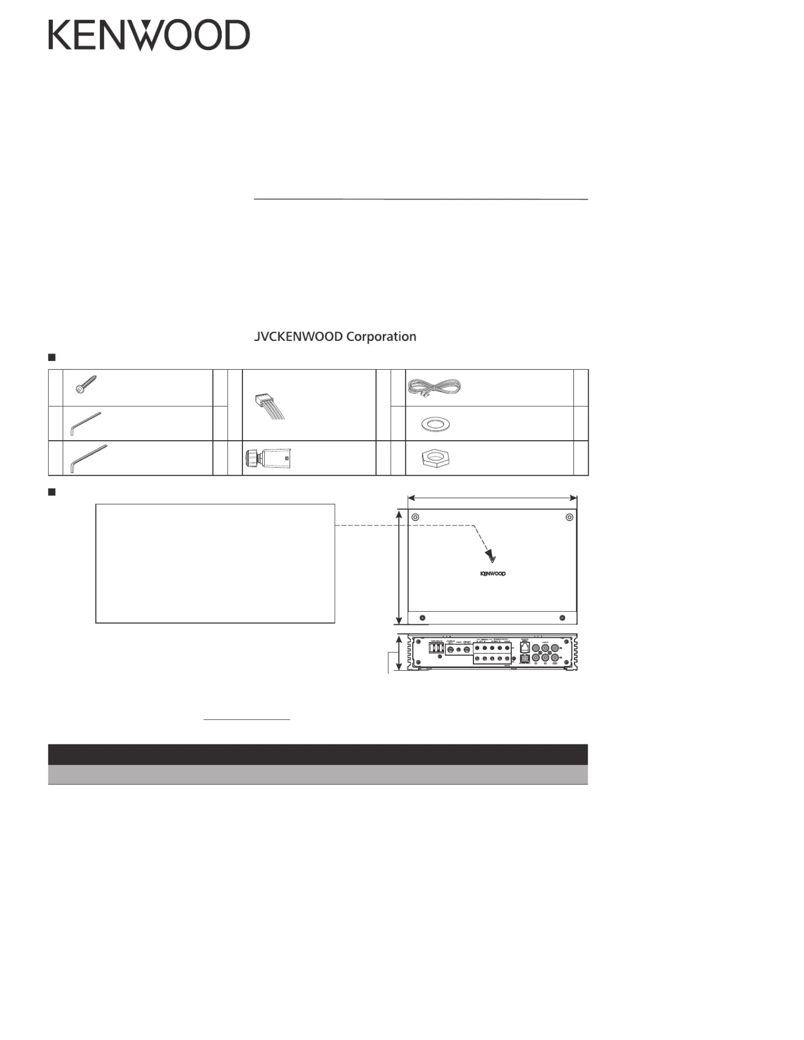
Dimensions / Dimensions / Dimensiones
248 mm (9-3/4”)
53 mm (2-1/16”)
169 mm (6-5/8”)
Accessories / Accessoires / Accesorios
①
Ø4×16 mm
Self-tapping screws
Vis taraudeuses
Tornillo autorroscantes
4
④
Speaker level input
cable
Câble d’entrée de
niveau d’enceinte
Cable de entrada
del nivel de
altavoces
1
⑥
Remote cable
Câble de la télécommande
Cable del mando a
distancia
1
②
2.5 mm
Hexagon wrench
Clé polygonale
Llave hexagonal
1
⑦
Washer
Rondelle
Arandela
1
③
4.0 mm
Hexagon wrench
Clé polygonale
Llave hexagonal
1
⑤
Remote controller
Télécommande
Controlador remoto
1
⑧
Hex nut
Écrou hexagonal
Tuerca hexagonal
1
248 mm (9-3/4”)
169 mm (6-5/8”)
Power indicator
When the power is turned on, the Power indicator
lights.
Indicateur d’alimentation
Lorsque l’alimentation est activée, l’indicateur d’ali-
mentation s’illumine.
Indicador de potencia
Cuando la alimentación se activa, el indicador de
potencia se ilumina.
169 mm (6-5/8”)
53 mm (2-1/16”)

Safety precautions
WARNING
To prevent injury or re, take the following precau-
tions:
• Mounting and wiring this product requires skills and
experience. For safety’s sake, leave the mounting and
wiring work to professionals.
• When extending the ignition, battery, or ground wires,
make sure to use automotive-grade wires or other
wires with the range of 14 mm
2
(AWG 6) to 21 mm
2
(AWG 4) to prevent wire deterioration and damage to
the wire coating.
• To prevent a short circuit, never put or leave any metal-
lic objects (such as coins or metal tools) inside the unit.
• If the unit starts to emit smoke or strange smells,
turn off the power immediately and consult your
KENWOOD dealer.
• Do not touch the unit during use because the sur-
face of the unit becomes hot and may cause burns if
touched.
CAUTION
To prevent damage to the machine, take the follow-
ing precautions:
• Be sure the unit is connected to a 12 V DC power sup-
ply with a negative ground connection.
• Do not open the top or bottom covers of the unit.
• Do not install the unit in a spot exposed to direct
sunlight or excessive heat or humidity. Also avoid
places with too much dust or the possibility of water
splashing.
• When replacing a fuse, only use a new one with the
prescribed rating. Using a fuse with the wrong rating
may cause your unit to malfunction.
• To prevent a short circuit when replacing a fuse, rst
disconnect the wiring harness.
NOTE
• If you experience problems during installation, consult
your KENWOOD dealer.
• If the unit does not seem to be working right, consult
your KENWOOD dealer.
Cleaning the unit
If the front panel gets dirty, turn o the power and wipe
the panel with a dry silicon cloth or soft cloth.
CAUTION
Do not wipe the panel with a hard cloth or a cloth damp-
ened by volatile solvents such as paint thinner and alco-
hol. They can scratch the surface of the panel and / or
cause the indicator letters to peel o.
To prevent battery rise
When the unit is used in the ACC ON position without
turning the engine ON, it depletes the battery. Use it after
starting the engine.
Protection function
The protection function is activated in the following
situations:
This unit is equipped with a protection function for
protecting this unit and your speakers from various acci-
dents or problems that can occur.
When the protection function is triggered, the power
indicator goes o and the amplier stops operating.
• When a speaker wire may be short-circuited.
• When a speaker output contacts ground.
• When the unit malfunctions and a DC signal is sent to
the speaker output.
• When the internal temperature is high and unit won’t
operate.
Wiring
• Take the battery wire for this unit directly from the bat-
tery. If it’s connected to the vehicle’s wiring harness, it
can cause blown fuses etc.
• If a buzzing noise is heard from the speakers when the
engine is running, connect a line noise lter (optional)
to each of the battery wire.
• Do not allow the wire to directly contact the edge of
the iron plate by using Grommets.
• Connect the ground wire to a metal part of the car
chassis that acts as an electrical ground passing elec-
tricity to the battery‘s negative terminal. Do not turn ⊖
the power on if the ground wire is not connected.
• Be sure to install a protective fuse in the power cord
near the battery. The protective fuse should be the
same capacity as the unit’s fuse capacity or somewhat
larger.
• For the power cord and ground, use a vehicle type
(reproof) power wring cord. (Use a power wiring cord
with the range of 14 mm
2
(AWG 6) to 21 mm
2
(AWG 4).
• When more than one power amplier are going to be
used, use a power supply wiring wire and protective
fuse of greater current-handling capacity than the total
maximum current drawn by each amplier.
Speaker selection
• Using speakers with smaller input ratings than the
amplier’s output power would result in smoke gener-
ation or equipment failure.
• The impedance of the speakers that are going to be
connected should be 2 Ω or greater (for stereo con-
nections, amplier SUB), or 4 Ω or greater (for bridged
connections). When more than one set of speakers are
going to be used, calculate the combined impedance
of the speakers and then connect suitable speakers to
the amplier.
<Example>
•
•
•
• I
• D
• B
• D
• D
•
•
• I
• I
•
•
•
•
•
• I
• D
•
• B
• F
•
• U
•
Combined
impedance

Installation / Installation / Instalación
Installation procedure
Since there are large variety of settings and
connections possible according to applications,
read the instruction manual well to select the
proper setting and connection.
1. Remove the ignition key and disconnect
the negative
⊖
terminal of the battery to
prevent short circuits.
2. Set the unit according to the intended
usage.
3. Remove the Dressing cover.
4. Connect the input and output wires of the
units.
5. Connect the speaker wires.
6. Connect the power wire, power control wire
and grounding wire following this order.
7. Install the installation ttings in the unit.
8. Attach the unit.
9. Attach the Dressing cover.
10. Connect the negative
⊖
terminal of the
battery.
CAUTION
• Do not install in the below locations;
(Unstable location, In a location that interferes
with driving, In a location that gets wet, In a
dusty location, In a place that gets hot, In a
place that gets direct sunlight, In a location
that gets hit by hot air)
• Do not install the unit under the carpet.
Otherwise heat build-up occurs and the unit
may be damaged.
• Install this unit in a location which allows
heat to easily dissipate. Once installed, do not
place any object on top of the unit.
• The surface temperature of the amplier will
become hot during use. Install the amplier
in a place where people, resins, and other
substances that are sensitive to heat will not
come into contact with it.
• When making a hole under a seat, inside the
trunk, or somewhere else in the vehicle, check
that there is nothing hazardous on the oppo-
site side such as a gasoline tank, brake pipe,
or wiring harness, and be careful not to cause
scratches or other damage.
• Do not install near the dashboard, rear tray, or
air bag safety parts.
• The installation to the vehicle should securely
fasten the unit to a place in which it will not
obstruct driving. If the unit comes o due to
a shock and hits a person or safety part, it may
cause injury or an accident.
• After installing the unit, check to make sure
that electrical equipment such as the brake
lamps, turn signal lamps and windshield wip-
ers operate normally.
Procédure d’installation
Etant donné que le nombre de réglages et de
raccordements est assez important, il importe
de prendre pleinement connaissance du mode
d’emploi.
1. Retirer la clé de contact et débrancher la
borne négative ⊖de la batterie pour éviter
les court-circuits.
2. Régler l’appareil en fonction de l’utilisation
désirée.
3. Déposer l’enjoliveur.
4. Raccorder les câbles d’entrée et de sortie de
l’appareil.
5. Raccorder les câbles de haut-parleur.
6. Relier, dans l’ordre, le câble d’alimentation,
le câble de commande d’alimentation et le
câble de masse.
7. Mettre en place les accessoires d’installation
sur l’unité.
8. Brancher l’unité.
9. Fixer l’enjoliveur.
10. Raccorder la borne négative de la ⊖
batterie.
ATTENTION
• Ne pas procéder à l’installation de l’appareil
si vous trouvez dans l’un des lieux suivants;
(Lieu instable, Lieu où la conduite du véhicule
peut être gênée, Lieu exposé à l’humidité,
Lieu exposé à la poussière, Lieu surchaué,
Lieu exposé directement à la lumière du jour,
Lieu exposé à l’air chaud)
• Ne pas recouvrir l’appareil d’une nappe, tapis,
etc; la chaleur qui s’accumulerait risque d’en-
dommager l’appareil.
•
Installer cet appareil à un emplacement tel
que la chaleur puisse se dissiper aisément.
Après l’installation, ne placer aucun objet sur
l’appareil.
• La surface de l’amplicateur va chauer pen-
dant l’utilisation. Installer l’amplificateur à
un endroit où des passagers, de la résine ou
d’autres substances sensibles à la chaleur
n’entreront pas en contact avec lui.
•
Lors du forage d’un trou sous le siège, à l’inté-
rieur du core ou partout ailleurs dans le véhi-
cule, vérier s’il n’y a pas d’élément dangereux
de l’autre côté, tel qu’un réservoir à carburant,
une conduite de frein, une gaine de câbles,
et faire attention de ne pas faire de gries ou
d’autres dégâts.
•
Ne pas l’installer près du tableau de bord, de
la plage arrière ou d’éléments de sécurité de
l’airbag.
•
Lors de l’installation dans un véhicule, l’appareil
doit être fermement fixé à un endroit ou il ne
gênera pas la conduite. Si l’appareil se détache
suite à un choc et heurte quelqu’un ou un élé
-
ment de sécurité, il peut occasionner des bles-
sures ou un accident.
• Après installation de l’appareil, s’assurer que
les différents équipements électriques tels
que lampes frein et les clignotants de direc-
tion fonctionnent normalement.
⑦Parts included
Pièces comprises
Partes incluidas
⑧Parts included
Pièces comprises
Partes incluidas
1. Remove the panel of
the vehicle.
2. Drill a 8 mm (5/16”)
hole.
3. R emove the kno b,
then insert the shaft
through the drilled
hole. Place the nut and
washer and x them.
4. Place the knob on the
shaft.
5. Attach the panel.
1. Démonter le panneau
du véhicule.
2. Percer un orifice de 8
mm (5/16”).
3. Déposer la molette,
puis insérer l'axe à
travers l'orifice percé.
Mettre en place et
serrer l'écrou et la ron-
delle.
4. Placer la molette sur
l'axe.
5. Fixer le panneau.
1. Retire el panel del vehí-
culo.
2. Taladre un oricio de 8
mm (5/16”).
3. Retire el mando y, a
continuación, inserte el
eje a través del oricio
perforado. Coloque la
tuerca y la arandela y, a
continuación, fíjelas.
4. Coloque el mando en
el eje.
5. Monte el panel.
8 mm (5/16”) hole
Orice de 8 mm (5/16”)
Oricio de 8 mm (5/16”)
Panel (thickness : MAX. 3.2 mm (1/8”))
Panneau (épaisseur: MAX. 3,2 mm (1/8”))
Panel (grosor: MAX. 3,2 mm (1/8”))
Installing the remote controller (⑤ Parts included)
Installation de la télécommande (⑤ Pièces comprises)
Instalación del controlador remoto (⑤ Partes incluidas)
①Parts included
Pièces comprises
Partes incluidas
Dressing cover
Enjoliveur
Cubierta de adorno
Installation board, etc. (thickness: 15 mm or more)
Tableau d’installation, etc. (épaisseur: 15 mm ou plus)
Tablero de instalación, etc. (grosor: 15 mm o más)
a
②Parts included
Pièces comprises
Partes incluidass
(2.5 mm)
①Parts included
Pièces comprises
Partes incluidas
Dressing cover
Enjoliveur
Cubierta de adorno
②Parts included
Pièces comprises
Partes incluidass
(2.5 mm)
⑦Parts included
Pièces comprises
Partes incluidas
⑧Parts included
Pièces comprises
Partes incluidas
8 mm (5/16”) hole
Orice de 8 mm (5/16”)
Oricio de 8 mm (5/16”)
Volume control
knob
Molette de réglage
du volume
Mando de control de
volumen
•
• I
•
•
•
•
• N
l
•
I
•
L
•
Produktspezifikationen
Marke: | Kenwood |
Kategorie: | Empfänger |
Modell: | Excelon X803-5 |
Brauchst du Hilfe?
Wenn Sie Hilfe mit Kenwood Excelon X803-5 benötigen, stellen Sie unten eine Frage und andere Benutzer werden Ihnen antworten
Bedienungsanleitung Empfänger Kenwood
19 Juli 2025
14 Juli 2025
5 Juli 2025
5 Juli 2025
5 Juli 2025
30 Mai 2025
30 Mai 2025
29 September 2024
10 September 2024
31 August 2024
Bedienungsanleitung Empfänger
- Atlas Sound
- Wet Sounds
- Axing
- Deaf Bonce
- Kopul
- Mercury
- Sagem
- Valueline
- Mobile Crossing
- Linn
- Grundig
- NVX
- Hegel
- JTS
- SoundTube
Neueste Bedienungsanleitung für -Kategorien-
19 Juli 2025
19 Juli 2025
19 Juli 2025
19 Juli 2025
19 Juli 2025
19 Juli 2025
19 Juli 2025
19 Juli 2025
19 Juli 2025
19 Juli 2025