Kichler Martell 86000MBK Bedienungsanleitung
Kichler Nicht kategorisiert Martell 86000MBK
Lies die bedienungsanleitung für Kichler Martell 86000MBK (4 Seiten) kostenlos online; sie gehört zur Kategorie Nicht kategorisiert. Dieses Handbuch wurde von 5 Personen als hilfreich bewertet und erhielt im Schnitt 5.0 Sterne aus 5 Bewertungen. Hast du eine Frage zu Kichler Martell 86000MBK oder möchtest du andere Nutzer dieses Produkts befragen? Stelle eine Frage
Seite 1/4
IS-86000-US
We’re here to help 866-558-5706
Hrs: M-F 9am to 5pm EST
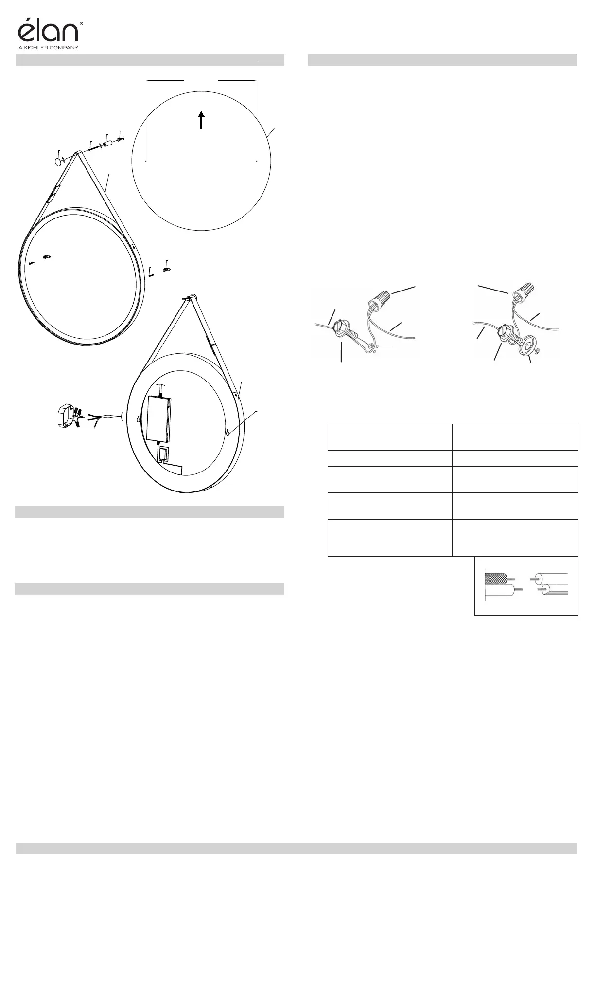
1) Use provided paper template[A] to locate the desired
mounng locaon for the mirror and to mark the locaons
required for the wall anchors.
2) Use a 15/64 inch drill bit to drill pilot holes at the locaons
marked in step 1 and insert wall anchors[C].
3) Screw all but 1/8 inch length of each wood screw[D] into the
wall anchors.
4) Grounding instrucons: (See Illus. a or b).
a) On xtures where mounng strap is provided with a hole
and two raised dimples, wrap ground wire from outlet
box around green ground screw, and thread into hole.
b) On xtures where a cupped washer is provided, aach
ground wire from outlet box under cupped washer and
green ground screw, then thread into mounng strap.
If xture is provided with ground wire, connect xture ground
wire to outlet box ground wire with wire connector aer
following the above steps. Never connect ground wire to black
or white power supply wires.
5) Make wire connecons. Reference chart below for correct
connecons and wire accordingly.
Connect Black or Red
Supply Wire to:
Connect White Supply
Wire to:
BlackWhite
*Parallel cord (round &
smooth)
*Parallel cord (square &
ridged)
Clear, Brown, Gold or
Black without Tracer
Clear, Brown, Gold or Black
with Tracer
Insulated wire (other
than green) with copper
conductor
Insulated wire (other
than green) with silver
conductor
*Note: When parallel wire (SPT
1 & SPT 2) are used. The neutral
wire is square shaped or ridged
and the other wire will be round
in shape or smooth (See illus.)
Neutral Wire
6) Hang mirror[B] by the keyhole slots[H] in the back of the
mirror. NOTE: the mirror should be oriented so that the
narrow poron of the keyhole faces up.
7) Extend the decorave strap[I] up and mark the hole locaon
for threaded tube[F].
8) Use a 15/64 inch drill bit to drill pilot hole and insert the wall
anchor[C].
9) Take the long screw[E] and place into the threaded tube and
secure to the installed wall anchor.
10) Slide the decorave strap over the installed threaded tube
and take the decorave cap[G] and thread into the installed
threaded tube.
11) To change the light output of your mirror, tap the switch on
the boom of the mirror or gently press the switch. The switch
is a touch dimming switch.
GREEN GROUND
SCREW
CUPPED
WASHER
OUTLETBOX
GROUND
FIXTURE
GROUND
DIMPLES
WIRE CONNECTOR
OUTLETBOX
GROUND
GREEN GROUND
SCREW
FIXTURE
GROUND
a
b
Fixture Diagram
Parts List
[A] Paper
Template
[B] Mirror
[C] Wall Anchors
[D] Wood Screw
[E] Long Screw
[F] Threaded
Tube
[G] Decorative
Cap
[H] Keyhole Slots
[I] Decorative
Strap
Cauons
CAUTION – RISK OF SHOCK –
Disconnect Power at the main circuit breaker panel or main
fusebox before starng and during the installaon.
WARNING:
This xture is intended for installaon in accordance with the
Naonal Electrical Code (NEC) and all local code specicaons.
If you are not familiar with code requirements, installaon by a
cered electrician is recommended.
DIMMING:
This LED xture is not compable with wall dimmer switches. Light
output can only be adjusted by using the touch dimming switch on
the boom of the mirror.
CLEANING:
Always be certain that electric current is turned o before cleaning.
• Only a so damp cloth should be used. Harsh cleaning
products may damage the nish.
Installaon Instrucons
This device complies with part 15 of the FCC Rules. Operaon is subject to the
following two condions:
1) This device may not cause harmful interference, and
2) This device must accept any interference received, including interference that
may cause undesired operaon.
Note: This equipment has been tested and found to comply with the limits for a
Class B digital device, pursuant to part 15 of the FCC Rules. These limits are designed
to provide reasonable protecon against harmful interference in a residenal
installaon. This equipment generates, uses and can radiate radio frequency
energy and, if not installed and used in accordance with the instrucons, may cause
harmful interference to radio communicaons. However, there is no guarantee that
interference will not occur in a parcular installaon. If this equipment does cause
harmful interference to radio or television recepon, which can be determined
by turning the equipment o and on, the user is encouraged to try to correct the
interference by one or more of the following measures:
• Reorient or relocate the receiving antenna.
• Increase the separaon between the equipment and receiver.
• Connect the equipment into an outlet on a circuit dierent from that to which
the receiver is connected.
• Consult the dealer or an experienced radio/TV technician for help.
FCC Informaon:
For warranty informaon please visit: kichler.com/warranty
22.0 [558.0]
B
A
C
D
G
E
F
C
H
I
TEMPLATE
UP
Produktspezifikationen
| Marke: | Kichler |
| Kategorie: | Nicht kategorisiert |
| Modell: | Martell 86000MBK |
Brauchst du Hilfe?
Wenn Sie Hilfe mit Kichler Martell 86000MBK benötigen, stellen Sie unten eine Frage und andere Benutzer werden Ihnen antworten
Bedienungsanleitung Nicht kategorisiert Kichler

7 Februar 2026
19 Januar 2026
17 Januar 2026
6 September 2024
6 September 2024
Bedienungsanleitung Nicht kategorisiert
Neueste Bedienungsanleitung für -Kategorien-
3 April 2026
3 April 2026
3 April 2026
3 April 2026
3 April 2026
3 April 2026
3 April 2026
3 April 2026
3 April 2026
3 April 2026