Klavis ComPair Bedienungsanleitung
Klavis
Nicht kategorisiert
ComPair
Lies die bedienungsanleitung für Klavis ComPair (9 Seiten) kostenlos online; sie gehört zur Kategorie Nicht kategorisiert. Dieses Handbuch wurde von 2 Personen als hilfreich bewertet und erhielt im Schnitt 5.0 Sterne aus 1.5 Bewertungen. Hast du eine Frage zu Klavis ComPair oder möchtest du andere Nutzer dieses Produkts befragen? Stelle eine Frage
Seite 1/9

Klavis ComPair
ComPair
ComPair
ComPairComPair user manual V1.0 Page of 1 9
ComPair
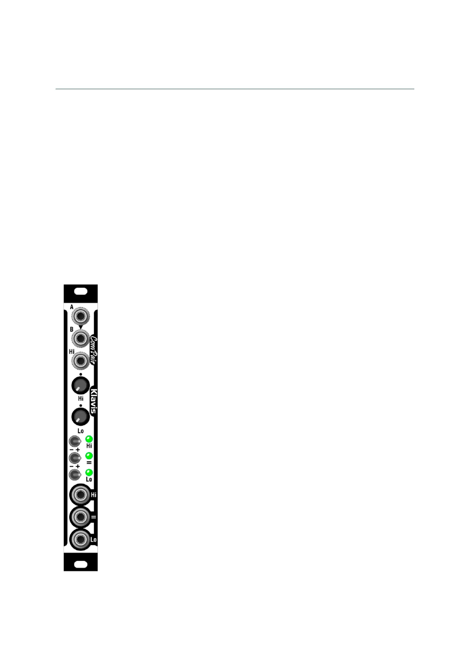
Dual/window threshold and signal comparator
Overview
The ComPair is a highly versatile while compact module that can handle all kind of voltage
comparison duties in audio, modulation and logic purposes.
Two sections can be used independently or combined as a unified window comparator. Window
comparison goes beyond simple “higher/lower than”, and checks if a signal is within a specific
range.
Besides the usual voltage setting potentiometers, there is an offset input jack on the first section
to allow voltage against voltage comparisons, leading to a 3-signal comparison capability .
A main differentiating feature of the ComPair is the possibility to invert and mute each of the
comparison results on the 3 output jacks. Dedicated LEDs indicate the current status of each
output.
Features
• Different usage modes
1. As two independent threshold- -signal comparators to
2. As a single window comparator
3. As a voltage- -voltage comparator to
4. As a 3-signal voltage comparator
• For each comparator
o Input and output jacks
o Threshold potentiometer
o Above/Below/Mute 3-position switch
o Signal active LED indication
• Window comparison has its dedicated switch and LED
• The first comparator has an additional input for signal- -signal to
comparison with offset.
• All outputs allow direct Oring by simple shorting via a multiple
• Compact module
• Aluminium front panel
• Compact and skiff-friendly module

Klavis ComPair
ComPair
ComPair
ComPairComPair user manual V1.0 Page of 2 9
Installation and security
Purpose
This module is meant for installation in a Eurorack-compliant chassis.
It adheres to Doepfer Eurorack mechanical and electrical specifications.
Do not attempt using this module in other mechanical or electrical contexts.
Installation
Before the installation, disconnect the mains power supply from your modular system.
Some power supplies are not safely isolated; there is a risk of injury!
See in the specifications if this module requires 5V from the supply rails. If 5V is needed and your
rack is not providing 5V, do not attempt connection!
Check that the current consumption requirements of this module, when added to your installed
set of modules do not exceed the available current from your supply. This is done by adding up
the current draw of all modules (mA) separately for each of 5V, 12V and -12V rails. If any of these 3
sums exceeds the available current of your supply for that voltage, do not connect the module to
your system; you need a stronger power supply.
The provided supply flat cable can only be inserted in the appropriate orientation at the back of
the module, so there is no risk of error on that end. However, you should pay attention to the
orientation of the cable in the socket of the supply PCB inside your chassis. Cheap sockets
without shrouding may allow you to plug in the connector the wrong way!
The red stripe on the cable should match a stripe printed on the supply board. The stripe also
indicates the -12V side. In case there is no stripe, a -12V marking is a safe indication of the
orientation.
Double check that the connectors are fully inserted and correctly oriented before switching on
the power supply. In case of an anomaly, switch off the power supply immediately and check
everything again.

Klavis ComPair
ComPair
ComPair
ComPairComPair user manual V1.0 Page of 3 9
Quick overview
The ComPair accepts analog input signals (Audio, LFO, …) and outputs digital signals (gate,
trigger, …). Inputting digital signals is allowed but usually less useful.
The module allows comparisons against a signal and either: a threshold, another signal, or a
window defined by high and low settings.
The module can be patched/used to get either:
• two distinct signal- -threshold comparators to
• one signal- -threshold comparator plus one signal- -signal + threshold comparator to to
• one signal- -window comparator to
• 3-signal comparison logic
The A and B sections are combined to create a third output (=), when used as a window
comparator.
By default, comparator A output is active (outputs positive voltage) only when the A signal is
above the threshold. Conversely, comparator B output is active when the B signal is the below
threshold. Finally, the window comparator output is active when the A signal is between the Hi
and Lo limits.
We see how input A is internally fed into input B when there is no Jack inserted into input B.
Section A offers a dynamic setting option thanks to a dedicated CV (Hi) input.
Sum
In Hi
Comp
In A
inverter
Comp
In B
inverter
Hi
Lo
A > Hi = 1
B < Lo = 1
inverter
(A < Hi) and (B > Lo) = 1
Out Hi
Out Lo
Out
Potentiometers
Threshold for comparators A (Hi) and B (Lo)
Potentiometers A / B set the threshold against which the A / B input voltage will be compared to.
Hi is for High threshold, and Lo for Low threshold.
Produktspezifikationen
Marke: | Klavis |
Kategorie: | Nicht kategorisiert |
Modell: | ComPair |
Brauchst du Hilfe?
Wenn Sie Hilfe mit Klavis ComPair benötigen, stellen Sie unten eine Frage und andere Benutzer werden Ihnen antworten
Bedienungsanleitung Nicht kategorisiert Klavis
29 Juli 2025
29 Juli 2025
5 September 2024
5 September 2024
31 August 2024
31 August 2024
31 August 2024
27 August 2024
9 August 2024
28 Mai 2024
Bedienungsanleitung Nicht kategorisiert
- Pure
- FitterFirst
- Alecto
- Chefman
- MotorScrubber
- Reebok
- Kayser
- EA Elektro Automatik
- Graef
- Hansgrohe
- Carry-on
- Gamma
- EM2GO
- Epson
- RAM Mounts
Neueste Bedienungsanleitung für -Kategorien-
30 Juli 2025
30 Juli 2025
30 Juli 2025
30 Juli 2025
30 Juli 2025
30 Juli 2025
30 Juli 2025
30 Juli 2025
30 Juli 2025
30 Juli 2025