König CMP-NWIPCAM31 Bedienungsanleitung
Lies die bedienungsanleitung für König CMP-NWIPCAM31 (129 Seiten) kostenlos online; sie gehört zur Kategorie Webcam. Dieses Handbuch wurde von 43 Personen als hilfreich bewertet und erhielt im Schnitt 4.8 Sterne aus 7 Bewertungen. Hast du eine Frage zu König CMP-NWIPCAM31 oder möchtest du andere Nutzer dieses Produkts befragen? Stelle eine Frage
Seite 1/129
CMP-NWIPCAM22
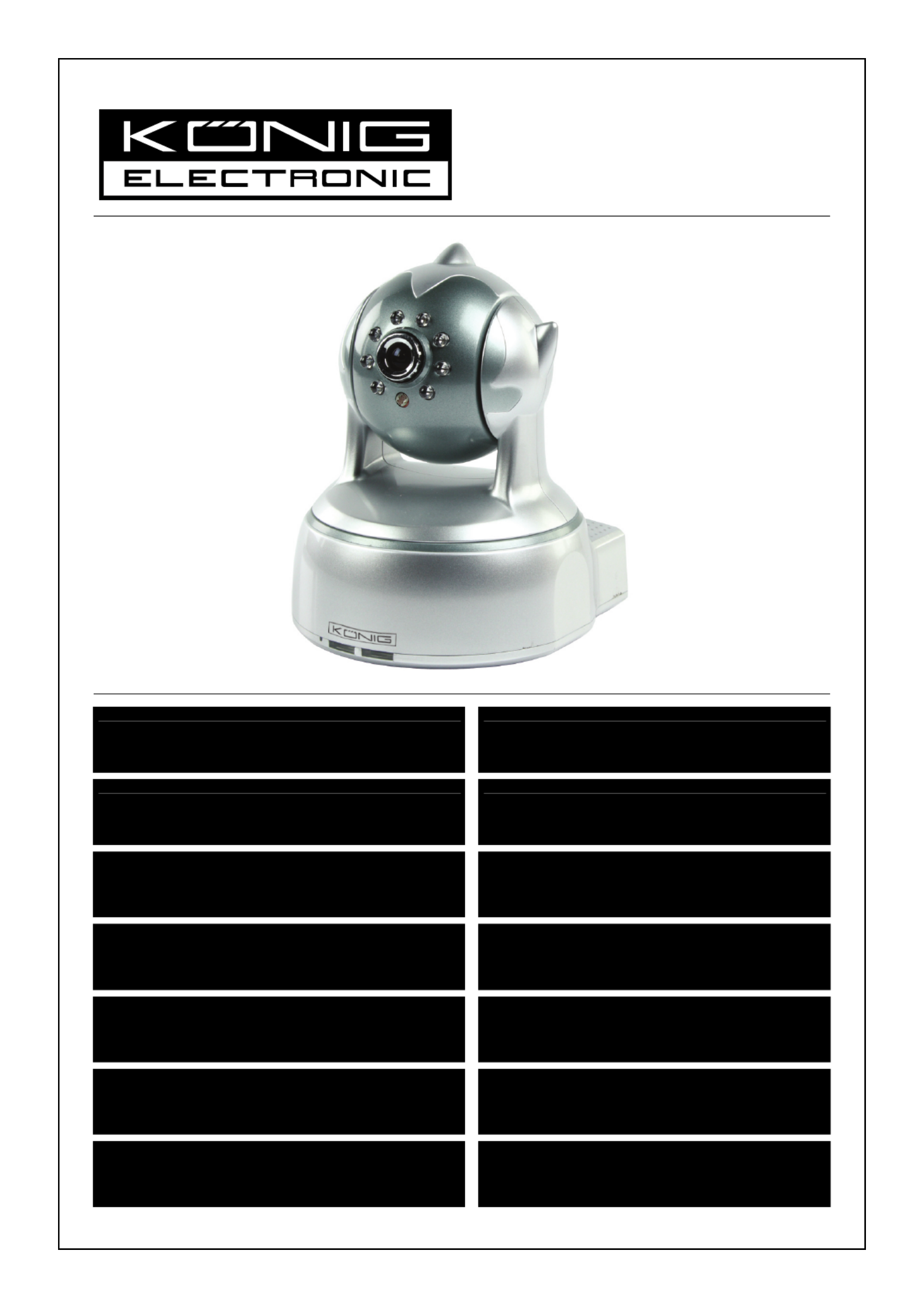
CMP-NWIPCAM31
MANUAL (p. 2)
IP Wireless Network Camera
ANLEITUNG (S. 11)
IP WLAN-Netzwerkkamera
MODE D’EMPLOI (p. 20)
Caméra à adresse IP de réseau sans fil
GEBRUIKSAANWIJZING (p. 29)
Draadloze IP-netwerkcamera
MANUALE (p. 38)
Videocamere di rete IP wi-fi
MANUAL DE USO (p. 47)
Cámara de Red IP Inalámbrica
HASZNÁLATI ÚTMUTATÓ (o. 56.)
Vezeték nélküli hálózati IP kamera
KÄYTTÖOHJE (s. 65)
Langaton IP-verkkokamera
BRUKSANVISNING (s. 74)
IP Trådlös nätverkskamera
NÁVOD K POUŽITÍ (s. 83)
IP bezdrátová síťová kamera
MANUAL DE UTILIZARE (p. 92)
Cameră video IP cu conectare wireless
ΕΓΧΕΙΡΙΔΙΟ XPHΣ ΣH (σελ. 101)
Ασύρματηκάμεραδικτύου IP
BRUGERVEJLEDNING (s. 110)
IP Trådløst netværkskamera
VEILEDNING (s. 119)
IP trådløstnettverkskamera
Produktspezifikationen
| Marke: | König |
| Kategorie: | Webcam |
| Modell: | CMP-NWIPCAM31 |
Brauchst du Hilfe?
Wenn Sie Hilfe mit König CMP-NWIPCAM31 benötigen, stellen Sie unten eine Frage und andere Benutzer werden Ihnen antworten
Bedienungsanleitung Webcam König

11 Oktober 2025
31 August 2024
8 August 2024
30 Juli 2024
20 Juli 2024
19 Juli 2024
Bedienungsanleitung Webcam
Neueste Bedienungsanleitung für -Kategorien-
1 April 2026
12 März 2026
7 März 2026
5 März 2026
1 März 2026
17 Februar 2026
21 Januar 2026
28 Dezember 2025
24 Dezember 2025
5 Dezember 2025