Rocstor WM12 Wireless Bedienungsanleitung
Rocstor Computermaus WM12 Wireless
Lies die bedienungsanleitung für Rocstor WM12 Wireless (66 Seiten) kostenlos online; sie gehört zur Kategorie Computermaus. Dieses Handbuch wurde von 10 Personen als hilfreich bewertet und erhielt im Schnitt 4.0 Sterne aus 8 Bewertungen. Hast du eine Frage zu Rocstor WM12 Wireless oder möchtest du andere Nutzer dieses Produkts befragen? Stelle eine Frage
Seite 1/66
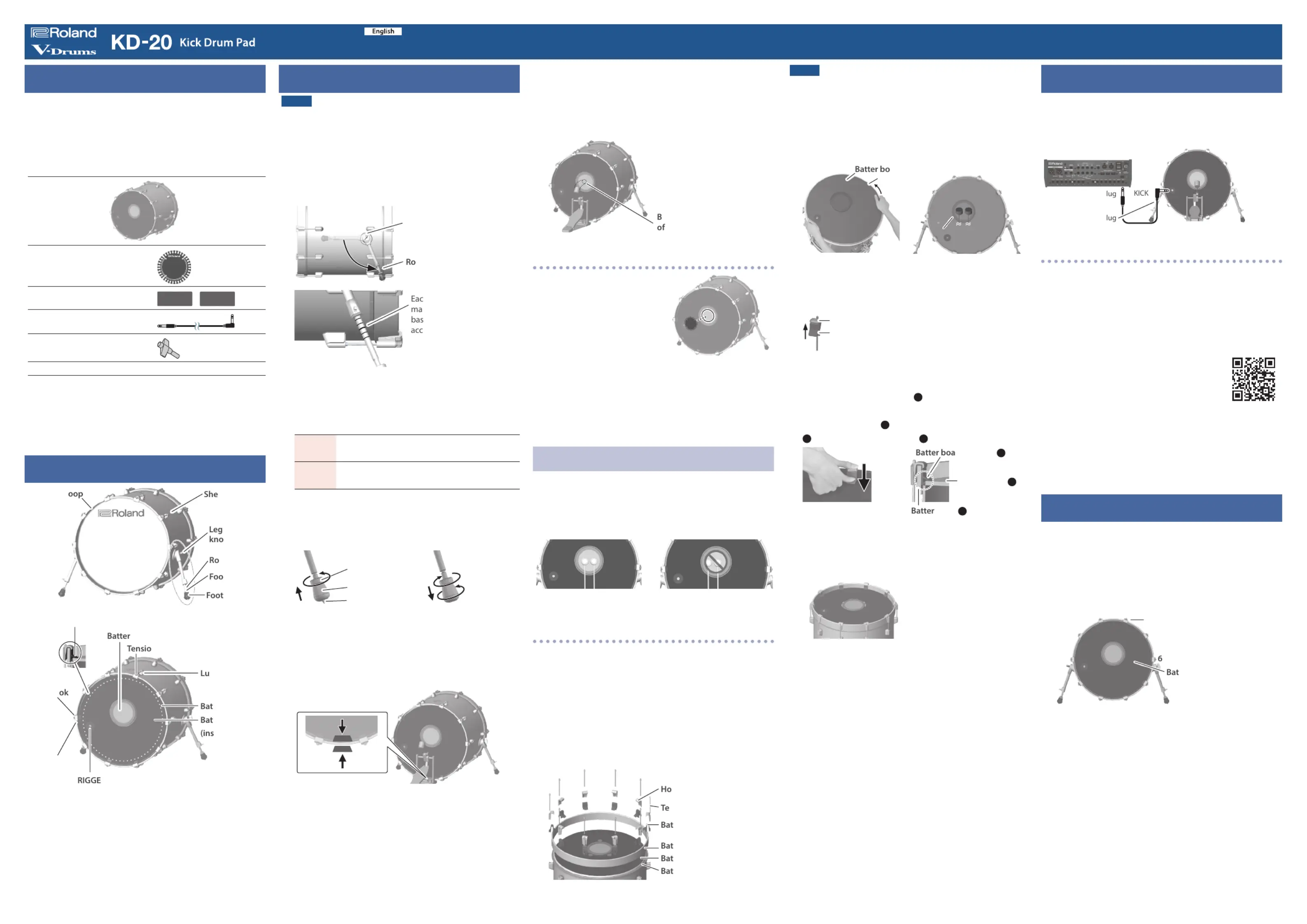
Checking the included items
After opening the package, check that all of the included
items are present. If anything is missing, contact your dealer.
* This package does not include a kick pedal. Attach a
commercially available kick pedal.
* The items in the package may dier if this product was
included as part of a Roland drum kit.
Main unit
Kick drum patch
(used with the felt beater to
protect the pad face (*1))
Wood hoop protector × 2
Connection cable
Drum key
Owner’s Manual
*1: A variety of commercially available beaters can be used,
such as felt, plastic, or wood types. Apply the included
kick drum patch to the pad’s surface if you are using a felt
beater. Note that felt beaters may leave felt marks in the
surface of the pad, even if you apply the kick drum patch.
Descriptions
Fron
Fron
Fron
Front head
t head
t head
t headFront head
H
fastener
b
d
t nut
Leg
ll
n bolt
g
head’s strike surface
Batter board stopper
Ho
ter board
ter head
ide)
TR OUTPUT jack
Batter hoop
* Do not insert your hand or ngers into the gap between the
batter board and the batter head striking surface. Doing so
might cause injury, damage, or malfunction.
Assembling the KD-20
NOTE
During assembly, take care that the weight of the bass drum
does not pinch your hand or foot.
1. Loosen the leg fastener knob, adjust the
angle of the leg, and then tighten the leg
fastener knob.
Using a drum key, adjust the length of the rods so that the
left and right are the same length.
Leg fastener knob
d
h rod has ve length
rks. Adjust the rod lengths
ed on the center marking,
ording to the kick pedal
you’re using.
2. Adjust the tip of the legs (spike/rubber)
appropriately for the surface on which you’re
placing the KD-20.
Spike
Soft oor
V-Drums mat (TDM series), carpet, etc.
Rubber
Hard oor
Wood ooring, concrete, etc.
If you loosen the foot nut and rotate the foot to raise it,
the spike will be exposed.
Tighten the foot nut to secure the position of the foot.
Foot nut
Foot
Spike
Exposing the spikeTightening the foot nut
* The tip of the spike is sharp; handle it with care.
* Using the spike leg tips on wood ooring may damage the
oor; the rubber leg tips should be used on wood ooring.
3. Ax the wood hoop protectors to the
position at which the kick pedal is attached.
Ax to both surfaces of the
batter hoop
* The adhesive of the wood hoop protector works better if you
apply it one day before attaching the kick pedal.
4. Mount the kick pedal.
Adjust the location at which the kick pedal is attached
so that the beater strikes the center of the batter head’s
strike surface; then securely fasten the kick pedal to the
KD-20.
* Take care not to pinch your ngers.
eater must hit the center
the striking surface
After attaching the kick
pedal, adjust the angle of the
legs and the length of the
rods as necessary.
Using a felt beater
To protect the batter head’s
strike surface, be sure to apply
the included kick drum patch to
the pad face if you are using a
felt beater.
When using a non-felt beater, you
can keep using the pad normally
with the patch still on.
* If you wish to remove the marks (adhesive) that remain
after you peel o the patch, wipe them o with a cloth and
rubbing alcohol.
* Do not use rubbing alcohol on any other parts besides the
batter head’s strike surface. Using rubbing alcohol on plastic
or wooden parts may cause discoloration or damage.
Using double kick pedals
The KD-20 can also be used with double kick pedals.
Adjust the striking points of the two beaters so that they are
at equal distances to the left and right of the batter head’s
strike surface.
Correct
Incorrect
If the beater’s striking point cannot be aligned
appropriately
Depending on the kick pedal, it might not be possible to
attach it to the bass drum so that the strike point of the two
beaters is located symmetrically to the left and right of the
center of the batter head’s strike surface.
In this case, use the following procedure to adjust the
position of the batter head’s strike surface.
1. Loosen the tension bolt, remove all of
the hooks/tension bolts, the batter board
stopper, and the batter hoop.
ter board
ter board stopper
nsion bolt
ok
ter head
ter hoop
NOTE
To avoid injury, damage, or malfunction, do not detach the
batter board and batter head from the shell. Take care not to
injure your hands or feet while working.
2. Rotate the batter head and board together,
and adjust them so that the beaters are
aligned to the center.
ard
Batter head
Align the beaters
Align the beaters
Align the beaters
Align the beaters Align the beaters
with the center
with the center
with the center
with the centerwith the center
3. Place the batter hoop back.
4. Attach the batter board stopper to the
hooks/tension bolts.
Hook / Tension bolt
Batter board stopper
5. Alternating between opposite sides and
using your ngers to press the hooks and
batter board stoppers
A
, insert the tension
bolts into the lugs while pressing the batter
board stoppers
A
in between the batter hoop
B
and the batter board
C
.
rd stopper
A
Batter board
C
hoop
B
Push down
6. Working alternately across opposite sides of
the drum, lightly tighten each tension bolt
until the hooks do not wobble.
5
10
83
4
4
4
44
1
2
2
2
22
6
7
7
7
77
9
9
9
99
7. Then tighten each tension bolt another 3/4
of a turn to secure the front head.
* If the batter head is not secured suciently, the sensor might
malfunction, or the sound of the strike might be too loud.
Connecting to the drum sound module
Connect the KD-20 to your drum sound module.
Use the included connection cable to make the connection.
Connect the L-shaped plug of the connection cable to the
TRIGGER OUTPUT jack of the KD-20.
(Example) V71
I-shaped p
L-shaped p
Recommended parameter settings
These are the recommended values for the trigger
parameters when using the KD-20 with various drum sound
modules.
If the “PAD TYPE” or “TRIG TYPE” of your drum sound module
provides a “KD-20” setting, choose “KD-20” If “KD-20” is not
one of the available values, refer to the support information
on the Roland website.
https://roland.cm/trigger_prm
You may need to adjust the trigger parameters depending
on how you’ve mounted the KD-20 and the location at which
you’ve installed it.
For details on editing refer to the owner’s manual of your
drum sound module.
Adjusting the head tension
Adjust the tension of the batter head before you play the
KD-20. You can vary the strike response (playing feel) by
adjusting the tension.
1. Adjust each tension bolt little by little,
working back and forth across the head in
the order shown in the illustration.
1
2
3
4
9
5
8
7
ter head
Tension bolt
10
* Fully tightening a tension bolt at only a single location will
produce uneven tensioning, which will make it impossible
to achieve correct strike response and may also cause
malfunctions.
2. Adjust each tension bolt so that the head is
tensioned evenly.
© 2025 Roland Corporation
* This document explains the specications of the product at the time
that the document was issued. For the latest information, refer to the
Roland website.
Before using this unit, carefully read the leaet “USING THE UNIT SAFELY” and “IMPORTANT NOTES”.
After reading, keep the document(s) where it will be available for immediate reference.
Owner’s Manual
Produktspezifikationen
| Marke: | Rocstor |
| Kategorie: | Computermaus |
| Modell: | WM12 Wireless |
Brauchst du Hilfe?
Wenn Sie Hilfe mit Rocstor WM12 Wireless benötigen, stellen Sie unten eine Frage und andere Benutzer werden Ihnen antworten
Bedienungsanleitung Computermaus Rocstor

30 März 2026
27 März 2026
27 März 2026
Bedienungsanleitung Computermaus
Neueste Bedienungsanleitung für -Kategorien-
3 April 2026
28 März 2026
28 März 2026
27 März 2026
24 März 2026
22 März 2026
21 März 2026
21 März 2026
20 März 2026
19 März 2026