RTS OKI Bedienungsanleitung
Lies die bedienungsanleitung für RTS OKI (2 Seiten) kostenlos online; sie gehört zur Kategorie Nicht kategorisiert. Dieses Handbuch wurde von 32 Personen als hilfreich bewertet und erhielt im Schnitt 4.3 Sterne aus 9 Bewertungen. Hast du eine Frage zu RTS OKI oder möchtest du andere Nutzer dieses Produkts befragen? Stelle eine Frage
Seite 1/2
Quick Start Guide
OKI - OMNEO Keypanel Interface KP 12 CLD
Included:
•OMNEOKeypanelModule
•RearPanel,KP12CLD,Expansion
•2-Screw,4-40x.25LG.
•3-Screw,PH,4-40x3/16LG.
•SafetyInstructionsST-CO
•OKIQuickStartGuide
•OKIDocumentationResourceDisk
Requirements:
Youmusthavethefollowing:
•PhillipsScrewdriver
•HexNutDriver
Firmware Requirements
•KP12CLDversion1.30
IMPORTANTThekeypanelrmwaremustbeupdatedbefore
youinstalltheOKImoduleintothekeypanel.
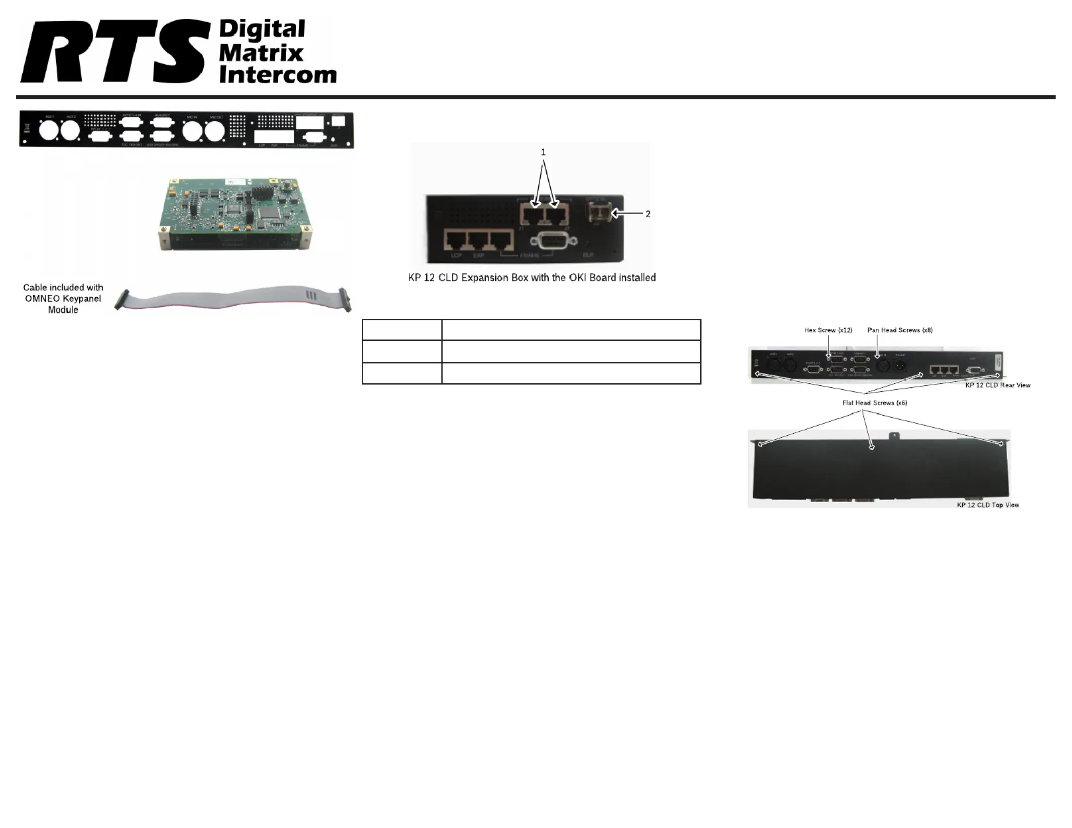
Reference View - OKI KP 12 CLD
Description
1.J1&J2RJ-45Connectors(2)
2.J3LCFiberConnector(Optional)
OKI Installation – KP 12 CLD
Toinstall the OKI board set for the KP 12 CLD,dothe
following:
NOTE:Becauseallthechangesaremadetothe
expansionbox,removetheexpansionboxfrom
theKP12CLDunit.
1.PowertheKP12CLDunit.off
2.RemovethefromtheKP12CLDexpansion box
unit.
NOTE:Steps3and4areonlynecessaryifanRCoption
isinstalled.
3.Usingahexnutdriver,removethe12 hex screws
fromtheKP12CLDexpansionbox.
4.Usingthesamescrewdriver,removetheeight (8)
pan head screwsfromtheKP12CLDexpansion
box.
5.UsingaPhillipsscrewdriver,removethesix (6) at
head screws fromKP12CLDexpansionbox.
F01U280811Rev0101/2013
Produktspezifikationen
| Marke: | RTS |
| Kategorie: | Nicht kategorisiert |
| Modell: | OKI |
Brauchst du Hilfe?
Wenn Sie Hilfe mit RTS OKI benötigen, stellen Sie unten eine Frage und andere Benutzer werden Ihnen antworten
Bedienungsanleitung Nicht kategorisiert RTS

2 Oktober 2025
1 Oktober 2025
1 Oktober 2025
1 Oktober 2025
25 September 2025
24 September 2025
9 Juni 2025
9 Juni 2025
8 Juni 2025
7 Juni 2025
Bedienungsanleitung Nicht kategorisiert
Neueste Bedienungsanleitung für -Kategorien-
3 April 2026
3 April 2026
3 April 2026
3 April 2026
3 April 2026
3 April 2026
3 April 2026
3 April 2026
3 April 2026
3 April 2026