Satco S11876 Bedienungsanleitung
Satco Nicht kategorisiert S11876
Lies die bedienungsanleitung für Satco S11876 (2 Seiten) kostenlos online; sie gehört zur Kategorie Nicht kategorisiert. Dieses Handbuch wurde von 3 Personen als hilfreich bewertet und erhielt im Schnitt 4.8 Sterne aus 5 Bewertungen. Hast du eine Frage zu Satco S11876 oder möchtest du andere Nutzer dieses Produkts befragen? Stelle eine Frage
Seite 1/2
WARNING: Risk of Fire or Electric Shock
• Disconnect power before installation or any maintenance of the xture.
• To avoid damage, falling, electric shock or re, do not modify the xture
or replace accessories without conrming with the supplier rst.
• Only authorized, qualied personnel should install this xture and
should follow the owner’s manual.
• Do not dismantle the xture without the supplier’s authorization.
• Do not touch the power supply when the xture is operating.
• For use in environments where an accumulation of non-conductive
dust on the xture may be expected.
•Suitable for indoor wet locations.
•As per UL STD 1598: The volume of a wiring compartment or junction box with
more then one conduit or cable entry shall be calculated using two 12AWG branch
circuit conductors entering, and two 12AWG branch circuit conductors leaving,
and two 12AW insulated grounding conductors.
IMPORTANT:This product must be installed in accordance with the applicable
installation code by a person familiar with the construction and operation of the
product and the hazards involved.
LED 4"& 6"SLIM FIT DOWNLIGHTS
REMOTE DRIVER, FLAT LENS
Models: S11874, S11875, S11876, S11877
Satco Products, Inc.
Brentwood, NY 11717
INSTALLATION
INSTALLATION AND SAFETY INSTRUCTIONS
IMPORTANT: Read before installing xture. Retain for future reference.
© Copyright 2023 Satco Products, Inc. 4/23 v1.0
ModelDimensionsShapeWatts VoltsCCTCRIFinish
S118744 inchesRound10W
120V
2700K
3000K
3500K
4000K
5000K
90Black
S118756 inchesRound12W
S118764 inchesSquare10W
S118776 inchesSquare12W
Fixture Includes:
1 LED Lamp
1 Junction Box
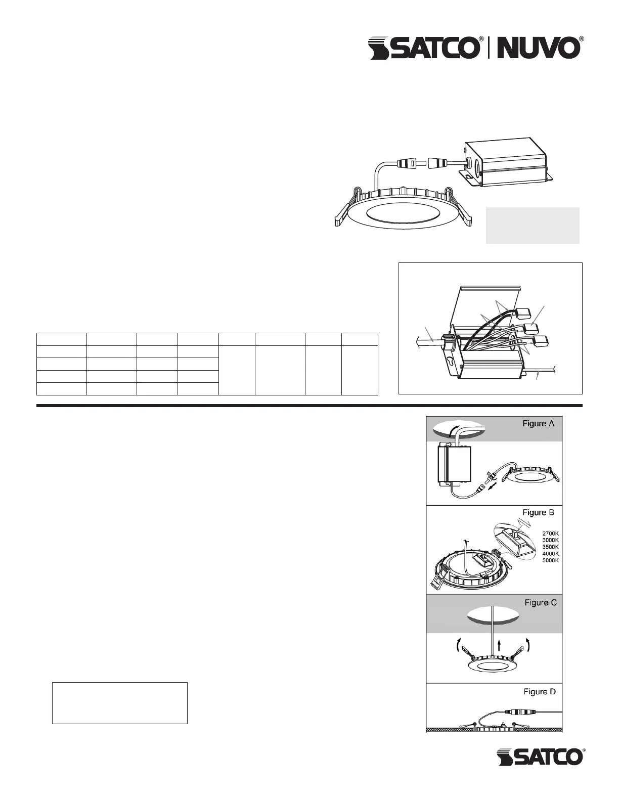
WIRING DIAGRAM
TOOLS REQUIRED: Hole saw, measuring tape and connector cables (as needed).
NOTE: Use extensions if necessary. Available connector cables are 6' (1.8m).
Connector cables are linkable.
1.Turn power OFF from the electrical panel before starting installation.
2.Cut a hole in the ceiling for the downlight in a suitable position. Refer to Hole Cut
Dimension chart (below).
3.Run the electrical wire from the switch (power supply wire) through the mounting hole.
Use NMD90 Romex or BX cable. See Figure A.
4.Open the Junction Box swing cover and remove the appropriate knockouts.
5.I nsert the power supply wire through the knockout and fasten with a cable connector
(not included).
6.Connect wires inside the Junction Box using t
he quick connect terminals. Connect
greenground with the green box wire. Connect the black and white power leads with
thematching black and white box wires. See Wiring Diagram.
7.Put all wires and connections back into the box and close the cover securely.
8.NewConstructionApplications:Junction Box shall be firmly secured to the studs,
joists orsimilarfixed structuralunits.
RemodelApplications: Do not require the Junction Box to be firmly secured to fixed
structural units. Remove the Junction Box tabs, then insert into ceiling.
9.Bend back the two torsion springs and slowly fit the fixture through the ceiling hole.The
torsion springs will pull the fixture into place. See Figures B & C.
10.Once installation is complete, turn power ON to confirm the fixture is working properly.
Hole Cut Dimensions:
4" xture = ø 4 3/16" (106mm)
6" xture = ø 6 3/16" (157mm)
Power supply
Cable to fixture
Green wires
Black wires
White wires
Quick connect
terminals
Produktspezifikationen
| Marke: | Satco |
| Kategorie: | Nicht kategorisiert |
| Modell: | S11876 |
Brauchst du Hilfe?
Wenn Sie Hilfe mit Satco S11876 benötigen, stellen Sie unten eine Frage und andere Benutzer werden Ihnen antworten
Bedienungsanleitung Nicht kategorisiert Satco

3 April 2026
3 April 2026
3 April 2026
2 April 2026
2 April 2026
2 April 2026
2 April 2026
2 April 2026
2 April 2026
1 April 2026
Bedienungsanleitung Nicht kategorisiert
Neueste Bedienungsanleitung für -Kategorien-
3 April 2026
3 April 2026
3 April 2026
3 April 2026
3 April 2026
3 April 2026
3 April 2026
3 April 2026
3 April 2026
3 April 2026