Simrad Recon UI Board Bedienungsanleitung
Simrad Nicht kategorisiert Recon UI Board
Lies die bedienungsanleitung für Simrad Recon UI Board (8 Seiten) kostenlos online; sie gehört zur Kategorie Nicht kategorisiert. Dieses Handbuch wurde von 33 Personen als hilfreich bewertet und erhielt im Schnitt 5.0 Sterne aus 5 Bewertungen. Hast du eine Frage zu Simrad Recon UI Board oder möchtest du andere Nutzer dieses Produkts befragen? Stelle eine Frage
Seite 1/8
Recon
™
Mount Controller UI Board
Installation Guide: EN
Document version: 001
⚠WARNING: This product must be installed in
accordance with the instructions provided. Failure to do
so could result in personal injury, damage to your vessel
and/or poor product performance.
⚠WARNING: Performing service or maintenance
without rst disconnecting the battery can cause product
damage, personal injury, or death due to re, explosion,
electrical shock, or unexpected motor starting. Always
disconnect the battery cables from the battery before
maintaining, servicing, installing, or removing motor
components.
In the box
• 1x Recon™ mount controller UI board
• 1x upper routing bracket
• 1x lower routing bracket
• 3x cable ties
• 5x M3-0.5 x 8, flange, hex, SS screws
• 2x #6 x 3/8 pan, T15 Torx
®
, SS screws
• 3x 1/4-28 x 3/8, button, hex, SS screws
• 6x M4-0.7 x 18, socket, hex, SS screws
• 2x #6 x 3/4, pan, T15 Torx
®
, SS screws
Tools needed
• #2 Phillips bit or screwdriver
• Knife or cutters
• 2 mm Allen key
• 3 mm Allen key
• 5/32 in Allen key
• T15 Torx
®
bit or screwdriver
• Torque wrench
• Dielectric grease
Introduction
The trolling motor’s sensors, cables, and user interface
lights and keys connect to the mount controller UI board
(mount controller board) inside the trolling motor mount.
Remove side plates and mount UI cover
1 Disconnect the trolling motor power cable from the
battery (or unplug the power cable if using a plug and
receptacle).
2 While your trolling motor is stowed or deployed, use a
#2 Phillips screwdriver to loosen the side plate screws
on both sides of the mount (A).
¼Note: The screws are retained by washers.
A
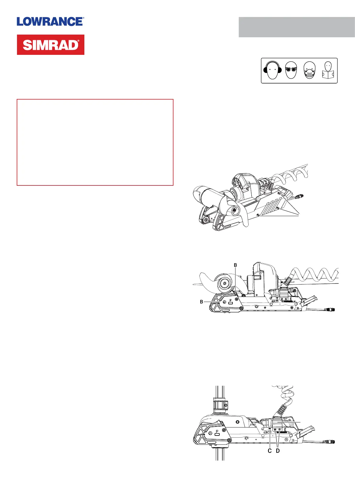
3 Remove the side plates, taking care not to damage the
locating tabs as they leave their slots (B).
B
B
4 Deploy the trolling motor.
5 Use a 2 mm Allen key to remove the screw from both
sides of the UI cover (C).
6 Use a 5/32 in Allen key to loosen the two screws (D) that
secure the coil cable bracket 2–3 full rotations. These
screws have a blue thread-locking compound applied to
them. Ease the coil cable bracket (E) outward from the
mount.
C
D
E
Produktspezifikationen
| Marke: | Simrad |
| Kategorie: | Nicht kategorisiert |
| Modell: | Recon UI Board |
Brauchst du Hilfe?
Wenn Sie Hilfe mit Simrad Recon UI Board benötigen, stellen Sie unten eine Frage und andere Benutzer werden Ihnen antworten
Bedienungsanleitung Nicht kategorisiert Simrad

17 März 2026
31 Oktober 2025
24 August 2025
23 August 2025
23 August 2025
23 August 2025
23 August 2025
23 August 2025
23 August 2025
23 August 2025
Bedienungsanleitung Nicht kategorisiert
Neueste Bedienungsanleitung für -Kategorien-
3 April 2026
3 April 2026
3 April 2026
3 April 2026
3 April 2026
3 April 2026
3 April 2026
3 April 2026
3 April 2026
3 April 2026