Simrad StructureScan 3D Thru-Hull Bedienungsanleitung
Simrad Fischfinder StructureScan 3D Thru-Hull
Lies die bedienungsanleitung für Simrad StructureScan 3D Thru-Hull (8 Seiten) kostenlos online; sie gehört zur Kategorie Fischfinder. Dieses Handbuch wurde von 20 Personen als hilfreich bewertet und erhielt im Schnitt 4.3 Sterne aus 5 Bewertungen. Hast du eine Frage zu Simrad StructureScan 3D Thru-Hull oder möchtest du andere Nutzer dieses Produkts befragen? Stelle eine Frage
Seite 1/8
Follow the precautions below for optimal
product performance and to reduce the risk of
property damage, personal injury, and/or death.
WARNING: Installation of the anti-rotation studs/screws
is mandatory! The anti-rotation studs/screws hold the fairing
firmly in place. Failure to install the anti-rotation studs/screws
may result in the fairing rotating while the boat is underway.
The effect may be violent movement and loss of steering.
WARNING: The transducer must be installed parallel to
the keel/centerline to ensure proper boat handling and
water flow under the transducer.
WARNING: Always wear safety glasses, a dust mask,
and ear protection when installing.
WARNING: Immediately check for leaks when the boat is
placed in the water. Do not leave the boat in the water
unchecked for more than three hours. Even a small leak
may allow a considerable amount of water to accumulate.
WARNING: SS70, SS141L with Fairing—The fairing
must be screwed to a block of wood before cutting. It is
too thin to cut safely without additional material. Failure
to do so may result in the fairing moving on the band saw.
WARNING: Fairing—Do not install a fairing that has
been mis-cut. Replace it.
•Cutting the fairing at an angle greater than the
maximum allowed will cut into the transducer and/or
anti-rotation pockets, thus weakening the fairing.
•Do not allow any gap between the fairing and the hull
that is greater than 1.5mm (1/16"). When the boat is
underway, water will enter any gaps and push against
the fairing with considerable force, possibly rotating it.
WARNING: Fiberglass hull—The transducer must be
installed in solid fiberglass, not in coring.
CAUTION: Never install a metal transducer on a vessel
with a positive ground system.
CAUTION: Never pull, carry, or hold the transducer by
the cable as this may sever internal connections.
CAUTION: Never strike the transducer.
17-427-02-rev. 0506/07/16
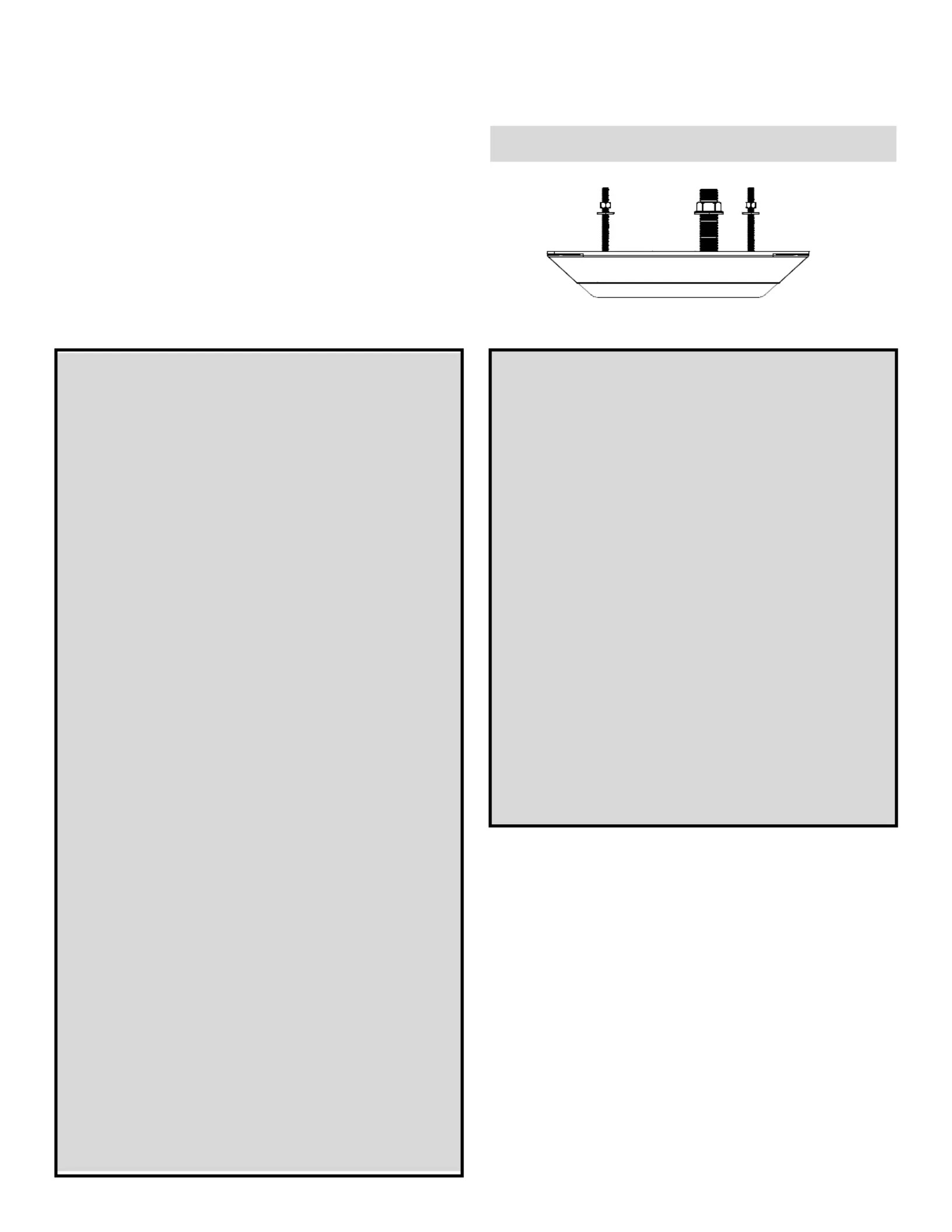
Thru-Hull withAnti-rotation Hardware
StructureScan™Transducers
Models: SS70, SS141L, SS147
Record the information found on the cable tag for future reference.
PN:___________________Date___________Frequency________kHz
Applications
•Stainless steel is compatible with all hull materials. Recommended
for aluminum hulls to prevent electrolytic corrosion, provided the
stainless steel transducer is isolated from the metal hull.
•Recommended for boats capable of speeds up to 30kn
(35MPH). Optimal speed is 1.5 - 8.5kn (2 - 10MPH).
•SS70, SS141L—A fairing is strongly recommended if the
deadrise angle of the hull exceeds 10°. The fairing can
accommodate a deadrise angle of up to 22°.
•SS70, SS141L—On a boat with a steep deadrise angle, a pair of
transducers, one on the port side and one on the starboard side,
can be installed and connected to the StructureScan module.
•SS147—Intended for stepped hulls, to be installed on a flat area
behind a step.
Identify Your Model
The model name is printed on the cable tag.
BOW
►
CAUTION: Stainless steel transducer in a metal hull—
Stainless steel must be isolated from a metal hull to
prevent electrolytic corrosion. Use the isolation sleeving
supplied.
CAUTION: Transducer Pair—Be sure to connect the
port-side transducer and the starboard-side transducer
to the correct terminals on the StructureScan module. If
the transducers are connected in reverse, the display will
not work properly.
CAUTION: SS147—The transducer must be installed on
a nearly flat hull behind a step. Do not install on a V-hull.
Do not install with a fairing. If the transducer protrudes
below the hull on a fairing, it will be susceptible to impact
that may damage the transducer and void the warranty.
If a fairing is needed, install an SS70 or SS141L.
CAUTION: Never use solvents. Cleaner, fuel, sealant,
paint, and other products may contain solvents that can
damage plastic parts, especially the transducer’s face.
IMPORTANT: Read the instructions completely before
proceeding with the installation. These instructions
supersede any other instructions in your instrument
manual if they differ.
fairing
SS141L
INSTALLATION INSTRUCTIONSOWNER’S GUIDE &
Produktspezifikationen
| Marke: | Simrad |
| Kategorie: | Fischfinder |
| Modell: | StructureScan 3D Thru-Hull |
Brauchst du Hilfe?
Wenn Sie Hilfe mit Simrad StructureScan 3D Thru-Hull benötigen, stellen Sie unten eine Frage und andere Benutzer werden Ihnen antworten
Bedienungsanleitung Fischfinder Simrad

23 August 2025
23 August 2025
23 August 2025
23 August 2025
23 August 2025
22 August 2025
22 August 2025
22 August 2025
22 August 2025
22 August 2025
Bedienungsanleitung Fischfinder
Neueste Bedienungsanleitung für -Kategorien-
2 März 2026
11 November 2025
7 Oktober 2025
7 Oktober 2025
6 Oktober 2025