Supermicro H14SRV-HLN4F Bedienungsanleitung
Supermicro Nicht kategorisiert H14SRV-HLN4F
Lies die bedienungsanleitung für Supermicro H14SRV-HLN4F (1 Seiten) kostenlos online; sie gehört zur Kategorie Nicht kategorisiert. Dieses Handbuch wurde von 4 Personen als hilfreich bewertet und erhielt im Schnitt 4.1 Sterne aus 6 Bewertungen. Hast du eine Frage zu Supermicro H14SRV-HLN4F oder möchtest du andere Nutzer dieses Produkts befragen? Stelle eine Frage
Seite 1/1
© 2026 Supermicro Computer Inc. All rights reserved. Reproduction of this document whether in part or in whole is strictly prohibited without Supermicro's written
consent. All Trademarks are property of their respective entities. All information provided is deemed accurate at the time of printing; however, it is not guaranteed.MNL-2864-QRG-100
SUPERMICR
R
Package Contents
• One Supermicro Motherboard
• One Quick Reference Guide
H14SRV-HLN4F Quick Reference Guide
WARNING: This product can expose you to chemicals including
lead, known to the State of California to cause cancer and birth
defects or other reproductive harm. For more information, go
to www.P65Warnings.ca.gov.
!
BAR CODE
BIOS LICENSE
REV:1.00
DESIGNED IN USA
1
2
1
A
C
C
A
1
C
A
A
C
JPW1
JMD2_SRW1
JMD1_SRW2
JMD1_SRW1
BT1
JMD2
JMD1
JHDT1
JGP1
JTPM1
M
MH3
MH4
MH2
MH5
MH6
JLANLED1
JD1
JP3
JSMB1
JPT1
JID3
JPL1
JVRM1
JWD1
JPF1
JBT1
LED1
LED3
LED2
PL1
JBM1
JL1
LED4
LEDM1
CPU
JPH1JCPLD1
USB0/1
Label
JIPMB1
SN
FANA
COM1
SATA1SATA0
M.2-C2
M.2-C1
FAN3
FAN2
CPU SLOT7 PCIe 5.0 x16
BAR CODE
UID-SW
mDP
LAN3/LAN4
LAN1/LAN2
USB2/3 (3.2 (5Gb))
NMIX
PWR
LEDLED
HDDNIC
12
NICUID
LED
PS
FAILRST
PWR
ON
JF1
FAN1
DIMMA2
DIMMA1
DIMMB2
DIMMB1
HDMI1
JPI2C1
JPW2
USB4/5 (3.2 (10Gb))
BMC_LAN
JF1
H14SRV-HLN4F
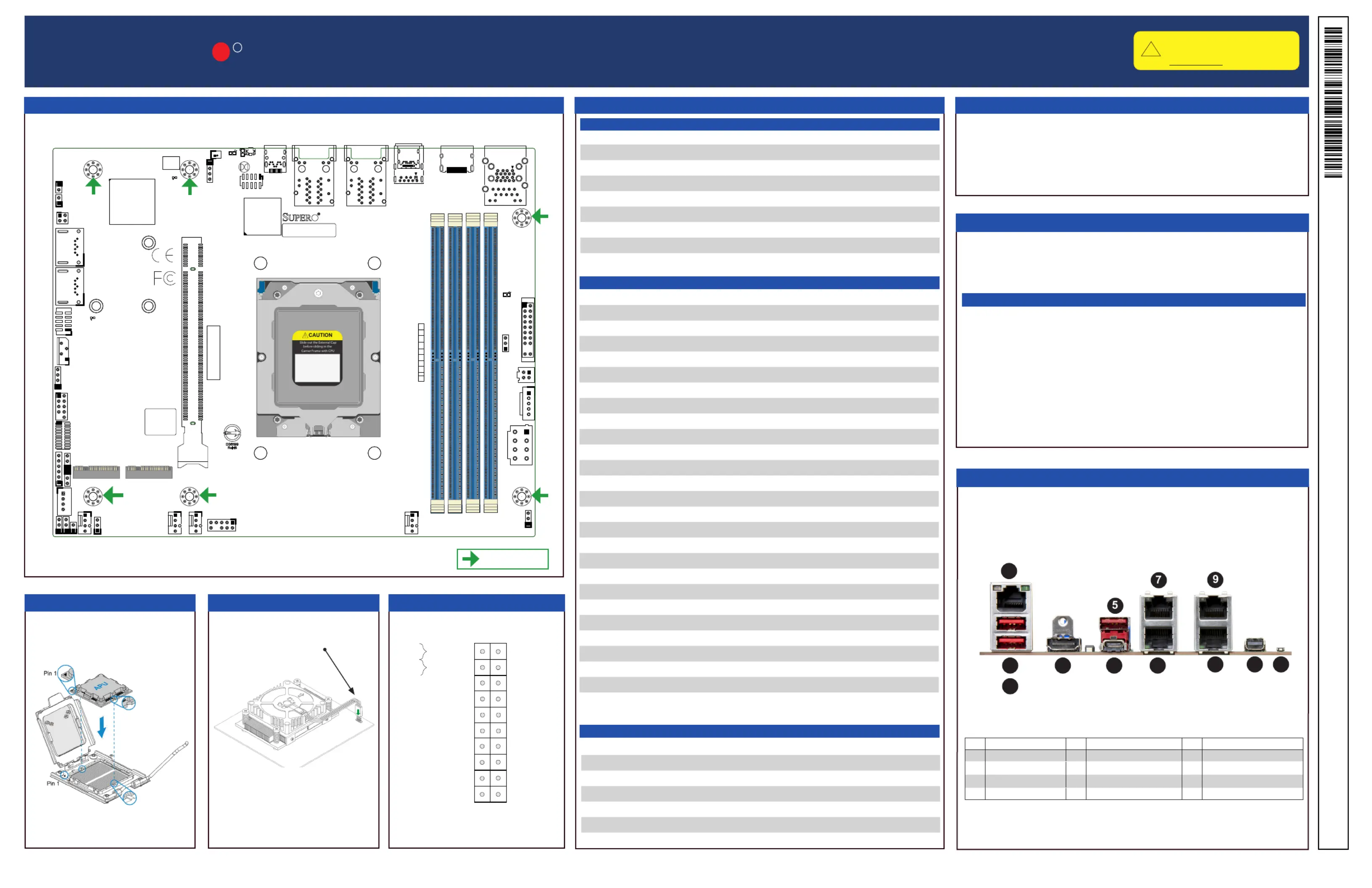
DIMM Memory Installation
Jumpers and Connectors
Memory Support
Motherboard Layout and Features
Front Control Panel (JF1)
Processor Support
The H14SRV-HLN4F motherboard supports up to 192 GB of DDR5 ECC UDIMM
memory with speeds of up to 5600 MT/s in four slots.
When installing memory modules, the DIMM slots should be populated in the fol-
lowing order: DIMMA1, DIMMA2, DIMMB1, and DIMMB2.
It is recommended to use DIMM modules of the same type, size, and speed. Mixed
DIMM speeds can be installed. However, all DIMMs will run at the speed of the
slowest DIMM. The motherboard will support an odd number amount of memory
modules. For best memory performance, install DIMM modules in pairs to activate
memory interleaving.
The H14SRV-HLN4F motherboard supports the AMD
®
EPYC
TM
4005 processor
with up to 16 cores and a Thermal Design Power (TDP) of 65 W in an AM5
Socket 1718.
ConnectorDescription
BMC_LANBMC LAN Port
BT1Onboard Battery
COM1COM Header
FAN1–FAN3, FANAFan Headers
HDMI1High Denition Multimedia Interface
JD1Speaker Header (Pins 1–4: Speaker)
JF1Front Control Panel Header
JGP1General Purpose I/O Header
JIPMB1External BMC I
2
C Header
JL1Chassis Intrusion Header
JLANLED1LAN Activity LED Header
JMD1M.2 M-Key PCIe 5.0 x4 (2280) Slot
JMD2M.2 M-Key PCIe 5.0 x4 (22110) Slot
JPH14-pin HDD Power Connector
JPI
2
C1Power System Management Bus (SMB) I
2
C Header
JPW14-pin +12 V Power Source
JPW28-pin +12 V CPU Power Connector (Required)
JSMB1System Management Bus Header
JTPM1Trusted Platform Module/Port 80 Connector
LAN1–LAN41 GbE (RJ45) LAN Ports
mDPMini DisplayPort
SATA0, SATA1SATA 3.0 Ports
UID_SWUnit Identier Button
USB0/1USB 2.0 Header
USB2USB 3.2 Port (5 Gb)
USB3, USB4/5USB 3.2 Ports (10 Gb)
LEDDescriptionStatus
LED1Power LEDSolid Green: Power On
LED2Unit Identier (UID) LEDSolid Blue: Unit Identied
LED3Power Fail/Fan Fail LEDSolid Red: Power Fail or Fan Fail
LED4CPLD HeartbeatBlinking Green: CPLD Normal
LEDM1BMC HeartbeatBlinking Green: BMC Normal
I/O Ports
1
8
6
4
3
2
1011
Fan Fail LED
20
NIC1 Link LED-
19
HDD LED-
PWR LED-
Key, no pin
GND
NMI Switch
Key, no pin
NIC2 Link LED-
HDD LED+/UID Switch+
Power Button
Reset Button
Reset
PWR
GND
GND
12
Power Fail LED-
UID LED-
Power Fail LED+
PWR LED+
NIC2 Link LED+
NIC1 Link LED+
12
Jumpers
Connectors
###DescriptionDescriptionDescription
1.BMC_LAN5.9.LAN4USB2 (3.2)
2.6.USB4 (3.2)USB 3.2 Gen2 Alt Mode10.LAN3
3.7.LAN2USB5 (3.2)11.mDP (BMC video display)
4.8.LAN112.HDMI PortUID Button
JumperDescriptionDefault Setting
JBM1Disable IPMI Shared LANOpen (Normal)
JBT1CMOS ClearOpen (Normal)
JID3POWER_LIMIT_SELPins 2–3 (Disable Power Limit)
JPF1Power Force OnPins 1–2 (Normal)
JPL1LAN1/2/3/4 Enable/DisablePins 1–2 (Enabled)
JPT1Onboard TPM 2.0 Enable/DisablePins 1–2 (Enabled)
JWD1Watchdog TimerPins 1–2 (Reset)
= mounting hole
Download Drivers and Utilities: https://www.supermicro.com/wdl/driver/
Refer to the Component Installation section of the user manual for information on jumpers, connectors, LED Indicators, memory support, and processor installation instructions.
Heatsink Installation
Processor Installation
Connect to the fan header
LED Indicators
Produktspezifikationen
| Marke: | Supermicro |
| Kategorie: | Nicht kategorisiert |
| Modell: | H14SRV-HLN4F |
Brauchst du Hilfe?
Wenn Sie Hilfe mit Supermicro H14SRV-HLN4F benötigen, stellen Sie unten eine Frage und andere Benutzer werden Ihnen antworten
Bedienungsanleitung Nicht kategorisiert Supermicro

3 April 2026
16 März 2026
6 Februar 2026
22 Januar 2026
22 Januar 2026
21 Januar 2026
18 Januar 2026
17 Januar 2026
14 Januar 2026
9 Oktober 2025
Bedienungsanleitung Nicht kategorisiert
Neueste Bedienungsanleitung für -Kategorien-
3 April 2026
3 April 2026
3 April 2026
3 April 2026
3 April 2026
3 April 2026
3 April 2026
3 April 2026
3 April 2026
3 April 2026