Supermicro SuperServer SYS-112H-TN Bedienungsanleitung
Supermicro
Server
SuperServer SYS-112H-TN
Lies die bedienungsanleitung für Supermicro SuperServer SYS-112H-TN (1 Seiten) kostenlos online; sie gehört zur Kategorie Server. Dieses Handbuch wurde von 25 Personen als hilfreich bewertet und erhielt im Schnitt 4.8 Sterne aus 13 Bewertungen. Hast du eine Frage zu Supermicro SuperServer SYS-112H-TN oder möchtest du andere Nutzer dieses Produkts befragen? Stelle eine Frage
Seite 1/1
1
1
1
2
2
1
1
1
1
2
3 4
1 2 3 4
1
2
3 4
56
1 2 3 4 5
6
Item t nDescrip io
1 P S 1ower upply
2 P S 2ower upply
3
Dedica edt BMC
LAN P tor
4
Two en U 3.2 GSB 1
P tsor
5 A P tVG or
6 UID Bu ontt
I m t t nte Slo Descrip io
PCIe 5.0 x M 16 AIO
S tlo
PCIe 5.0 x S t 16 lo
(FH, 6. L)6”
PCIe 5.0 x S t 16 lo
(FH, . L)12 3”
S t 3 cat (FH, lo lo ion
12 3”L). *
JFP1
MH5
SRW1
JPWR8
JPWR9
JIO1
J4
FAN5
FAN4 FAN3
FAN2
JMCIO_PE8B1 JMCIO_PE8A1
BAR CODE
BAR CODE
2242
2260
2280
22110
2242
2260
2280
22110
JSTBFAN
M.2_MH4
M.2_MH3
JTPM1
JRK1
M.2-C2
JNCSI1
JL1
DESIGNED IN USA
X14SBH
REV:1.01
BAR CODE
BAR CODE
BIOS LICENSE
2
J3
FAN10
JP2
JMCIO_PE7A1 JMCIO_PE7B1
JPWR5
JPWR6
JPWR7
LED6
JBT1
J10
BT1
LED4
JNVI2C1
JBPNI2C1
FAN8
FAN7
FAN6
JMCIO_PE5A1
JMCIO_PE5B1
M.2-C1
M.2_MH1
M.2_MH2
P1 AIOM PCIe 5.0 x16
LED1
LED3
JAIOM1
FAN9
JMCIO_PE6B1
P1 SLOT 2
JMCIO_PE6A1
P1_PE4 8–15 VPP I²C
P1_PE4 0–7 VPP I²C
SRW2
FAN1
JNVI2C2
JBPNI2C2
JPWR10
JPWR11
JB1
JPT1
JB2
JPWR2
JPWR1
JPSU1
MH3
J35
CPU
DIMMD1
DIMMD2
DIMMC1
DIMMC2
DIMMB1
DIMMB2
DIMMA1
DIMMA2
DIMME2
DIMME1
DIMMF2
DIMMF1
DIMMG2
DIMMG1
DIMMH2
DIMMH1
BMC
JPSU2
JTIMED
JSXB0
CUT OUT
CUT OUT
CUT OUT
CUT OUT
CUT OUT
JROU1
JPFR3
JPFR1
JPFR2
JP1
JCP1
JSPD1
P1 SLOT1 PCIe 5.0 x16
JDBG1
J4CSBMSEL
JVRM1
JRSI2C1 USB2/3
JAIOM2SB1
JPWR3
JPWR4
Rev. 1.0
Rev. 1.0
LBL-2758-T-QRG
LBL-2758-B-QRG
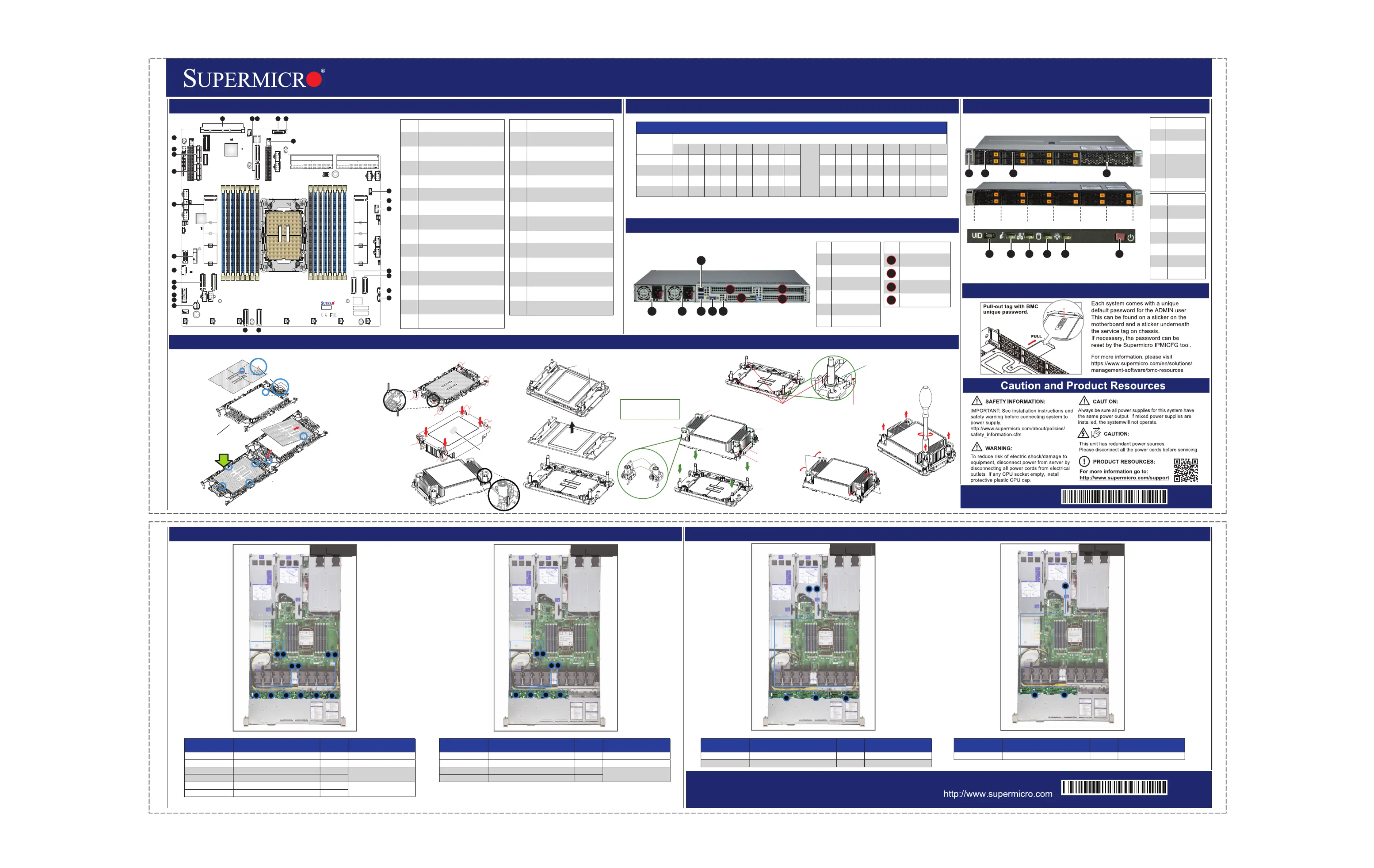
Rear View
System Information
CPU Installation, supporting a single Intel® Xeon® 6 Processor (LGA 4710)
Board Layout Memory Support
NVMe Drive Cable Routing Storage AOC Drive Cable Routing
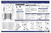
SuperServer SYS-112H-TN Quick Reference Guide
8 NVMe
12 SAS
8 SAS
12 NVMe
BMC Label
No te: Please refer to user manual for memory module [rank] and [DRAM density] requirements when using Intel® Xeon® 6 CPU.
4
1
2 3
5
6
7
8
12
16
13
1415
10
11
9
18
19
17
20
21
22
24
25
26
27
23
I m t nte Descrip io
1
JAIOM1: PCIe 5.0 x16 lo AIOM S t
Connector
2
P VME /131_N 12 : P 5.0 x8 Cle
MC Conne or 1_ 0-7IO ct (P PE6 )
3
P VME /151_N 14 : PCIe 5.0 x8
MC Conne or 1_ 8-15IO ct (P PE6 )
4JNCSI1: NC-SI rHeade
5JL1: Int s rru ion Heade
6
P1 2SLOT : PCIe 5.0 S t x16 4C lo
Connector
7
JRK1: Intel VROC R D Key AI
Header
8
M. 22-C : M.2 PCIe 5.0 Int face er
(M- 25key 110 22/ 110 2280/ )
9 : M orJ M1TP TP Connect
10
P VME /191_N 18 : PCIe 5.0 x8
MC Conne or 1_ 8-15IO ct (P PE8 )
11
P VME /171_N 16 : P 5.0 x8 Cle
MC Conne or 1_ 0-7IO ct (P PE8 )
12
JN ²CVI 2: NVMe 2C Heade I r
Channel 2
13
JB ²CPNI 2: N IBP 2C Heade r
Channel 2
14
P VME 0/11_N : P 5.0 IO Cle x8 MC
Conne or 1_ct (P PE4
)0-7
I m t nte Descrip io
15
P VME 2/31_N : P x8 O Cle 5.0 MCI
Conne or 1_ 8-15ct (P PE4 )
16
JN ²CVI 1: NVMe 2C Heade I r
Channel 1
17
JB ²CPNI 1: N BP I2C Heade r
Channel 1
18 : U 3.2 G r US /3B2 SB en1 Heade
19
P VME 6/71_N : PCIe 5.0 IO x8 MC
Conne or 1_ 8-15ct (P PE5 )
20
P VME 4/51_N : P x8 O Cle 5.0 MCI
Conne or 1_ 0-7ct (P PE5 )
21
J 1FP : F t t P l ron Con rol ane
Header
22 : O Ba yBT1 nboard CMOS tter
23
M. 12-C : M.2 PCIe 5.0 Int f e er ac
(M- 25key 110 22/ 110 2280/ )
24
P VME /111_N 10 : P 5.0 x8 Cle
MC Conne or 1_ 8-15IO ct (P PE7 )
25
P VME 8/91_N : P x8 O Cle 5.0 MCI
Conne or 1_ 0-7ct (P PE7 )
26
P1 1SLOT : PCIe 5.0 S t x16 4C lo
Connector
27
J 1IO : st B d Sy em I/O oar
Conne or MCct ( U BVGA, SB, NIC)
DI eMM Popul ionat Guid
Type
Cha el nn
H1 H2 G1 G2 F1 F2 E1 E2
CPU
A2 A1 B2 B1 C2 C1 D2 D1
2 DI sMM
V V
4 DI sMM
V V V V
8 DI sMM
V V V V V V V V
16 MM DI s
V V V V V V V V V V V V V V V V
A
Rotating Wire
1
2
Peek Nut
a
c
b
d
B. Assembling the Processor Heatsink Module (PHM)
1. If this is a new heatsink, the
thermal grease
has been preapplied.
Otherwise, apply the
proper amount of
thermal grease.
2. Hold the processor
carrier assembly so
the processor's gold
contacts are facing up,
then align the holes
of the processor
carrier assembly with the
holes on the heatsink.
Press the processor
carrier assembly down
until it snaps into place.
The plastic clips of the
processor carrier
assembly will lock at the
four corners.
3. Examine all corners to ensure
that the plastic clips on the processor
carrier assembly are firmly attached
to the heatsink.
A. Creating the Intel Xeon 6 CPU Carrier Assembly
1. Locate small gold triangle
(Pin 1) on processor
and corresponding
hollowed triangle
on carrier.
Pin 1
Make sure the lever
is pressed down before
installing the processor.
A
B
Pin 1
a
c
b
d
A
C
B
D
Processor Carrier Assembly
(Upside Down)
Triangle on the
processor carrier
Triangle on the CPU
Thermal grease
C. Preparing the CPU Socket for Installation
Gently pull off the plastic
protective cover by one
corner to remove it
from the CPU
socket.
D. Installing the Process Heatsink Module
1. Locate four threaded fasteners (a, b, c, d) on the CPU socket.
4. With a t30-bit screwdriver, tighten
all PEEK nuts in the sequence of
A, B, C, and D with even
pressure not greater than 8.0 in-lbf.
(0.904 N-m).
A, B, C, D: Peek Nut
1, 2, 3, 4: Rotating Wire
a, b, c, d: Threaded Fastener
Peek Nut
(Unlatched)
(Latched)
Rotating Wire
C
D
B
Rotating Wire
3
Rotating Wire 4
Rotating Wire
Gr absip T
a
b
c
d
(a, b, c, d: Threaded Fasteners) CPU Socket Pin1
Th adere
d
F eneast
r
CPU Socket
3. Press all four rotating wires outward to latch
the PHM onto the CPU socket.
Rotating
Wire
Rotating
Wire
2. Locate four PEEK nuts (A, B, C, D) and four rotating wires
(1, 2, 3, 4) on the heatsink as shown below. Gently place
the heatsink on the CPU socket, making sure that each
nut is properly aligned with its corresponding threaded
fastener.
A
B
C
D
2. Using the
triangles as a
guide, carefully
align and place
Point A of the
processor into
the carrier.
Gently snap into
place to
fasten onto
Point B.
2
3
1
4 6
5
A1
1
2
3
* Slot availability depends on system
configuration.
1
A1
2
3
Front View & Interface
2 3
1
4
6 7
5
8 9 10
HDD 0 HDD 2 HDD 4 HDD 6 HDD 8 HDD 10
HDD 1 HDD 3 HDD 5 HDD 7 HDD 9 HDD 11
I m t nte Descrip io
1 U 3.0 P tSB or
2
F t t l ron Con ro
P lane
3
S vice et er /Ass
Tag wi th BMC
Pa d sswor
Reset
4
St I/orage O
Bays
I m t nte Descrip io
5
UID Bu / tton
B setMC Re
6
Inf n ormatio
LED
7 NIC LED
8 LEDHDD
9 P LEDower
10 P Bu onower tt
C or on onnect
Bo dar Card/
Back ser Dr ve Ba MC Caplane/Ri a rtnd Po i y S bl P/e N
P NVME0/1 ( VME S11_ CN1 BPN-N 5-H 19N- 8L 0- L-MCIO-1330M5S ) 1 CB L
P NVME2/3 ( VME S11_ CN2 BPN-N 5-H 19N- 8L 2- L-MCIO-1330M5S ) 3 CB L
P NVME4/5 ( VME S11_ CN3 BPN-N 5-H 19N- 8L 4-S ) 5
CB FR -JL-MCIO-1464M5 FB
P NVME6/7 ( VME S11_ CN4 BPN-N 5-H 19N- 8L 6-S ) 7
P NVME /17 ( VME S11_ 16 CN1 BPN-N 5-H 19N- 4R 8-S ) 9
CB FRFBL-MCIO-1439M5
P NVME /19 ( VME S11_ 18 CN2 BPN-N 5-H 19N- 4R 10-S ) 11
C or on onnect
Bo dar Card/
Back ser Dr ve Ba MC Caplane/Ri a rtnd Po i y S bl P/e N
P NVME0/1 ( VME S11_ CN1 BPN-N 5-H 19N- 8L 0- L-MCIO-1330M5S ) 1 CB L
P NVME2/3 ( VME S11_ CN2 BPN-N 5-H 19N- 8L 2- L-MCIO-1330M5S ) 3 CB L
P NVME4/5 ( VME S11_ CN3 BPN-N 5-H 19N- 8L 4-S ) 5
CB FR -JL-MCIO-1464M5 FB
P NVME6/7 ( VME S11_ CN4 BPN-N 5-H 19N- 8L 6-S ) 7
C or on onnect
Bo dar Card/
Back ser Dr ve Ba MC Caplane/Ri a rtnd Po i y S bl P/e N
SAS AOC CN1 JSM1/JSM2 (BPN-NVME5-HS119N-S8L) 7 CB T0- L-SAS -1273L -10P 0
SAS AOC CN2 JSM1 (BPN-NVME5-HS119N-S4R) 11 CB T P 08- L-SAS -1262L -10
C or on onnect
Bo dar Card/
Back ser Dr ve Ba MC Caplane/Ri a rtnd Po i y S bl P/e N
SAS AOC CN1 JSM1/JSM2 (BPN-NVME5-HS119N-S8L) 7 CB T0- L-SAS -1273L -10P 0
Produktspezifikationen
| Marke: | Supermicro |
| Kategorie: | Server |
| Modell: | SuperServer SYS-112H-TN |
Brauchst du Hilfe?
Wenn Sie Hilfe mit Supermicro SuperServer SYS-112H-TN benötigen, stellen Sie unten eine Frage und andere Benutzer werden Ihnen antworten
Bedienungsanleitung Server Supermicro
7 August 2025
7 August 2025
7 August 2025
7 August 2025
7 August 2025
7 August 2025
7 August 2025
Bedienungsanleitung Server
- Synology
- Ibm
- Acer
- Intellinet
- Digitus
- Blackmagic Design
- EXSYS
- FLIR
- Totolink
- Fujitsu
- Siig
- AMX
- Opengear
- ELAC
- Dell
Neueste Bedienungsanleitung für -Kategorien-
4 August 2025

4 August 2025
4 August 2025

4 August 2025
4 August 2025
4 August 2025

4 August 2025

4 August 2025

4 August 2025
3 August 2025