Supermicro X14SBGM Bedienungsanleitung
Supermicro Nicht kategorisiert X14SBGM
Lies die bedienungsanleitung für Supermicro X14SBGM (1 Seiten) kostenlos online; sie gehört zur Kategorie Nicht kategorisiert. Dieses Handbuch wurde von 21 Personen als hilfreich bewertet und erhielt im Schnitt 4.7 Sterne aus 7 Bewertungen. Hast du eine Frage zu Supermicro X14SBGM oder möchtest du andere Nutzer dieses Produkts befragen? Stelle eine Frage
Seite 1/1
S
UPERMICR
R
© 2025 Supermicro Computer Inc. All rights reserved. Reproduction of this document whether in part or in whole is strictly prohibited without Supermicro's written
consent. All Trademarks are property of their respective entities. All information provided is deemed accurate at the time of printing; however, it is not guaranteed.
Package Contents
• One Supermicro Motherboard
• One Quick Reference Guide
X14SBGM Quick Reference Guide
MNL-2742-QRG-100
WARNING: This product can expose you to chemicals including
lead, known to the State of California to cause cancer and birth
defects or other reproductive harm. For more information, go
to www.P65Warnings.ca.gov.
!
JVRM1
JPCIe5A1
JPCIe5B1
X14SBGM
BAR CODE
JPCIe8A1JPCIe8B1
JPCIe4A1
JPCIe4B1
+
REV:1.01
DESIGNED IN USA
BIOS LICENSE
BAR CODE
MH4
JBT1
JNVVPP1
JP1
JDP1
JNCSI1
MH1
JI3CSW1
LED1
J42
JDBG1
JCOM1
FAN1
LE6
LE7
PWR6
JP6
FAN2
FAN3
FAN4
FAN5
J36
MH7
MH2
FAN6
FAN7
FAN8
JPME2
JPFR3
JPFR2
LE8
J7
JPWR3
JPWR2
JPWR5
JPWR5
MH3
JPDB1JRSI2C1JNVI2C1
J34
JLC1
JCPLD1
JBMC1
MCIO 5B P1_PE5 8–15
MCIO 5A P1_PE5 0–7
J35
JFP3
BT1
LED2
MCIO 3B P1_PE3 8–15
MCIO 3A P1_PE3 0–7
MCIO 7B P1_PE7 8–15
MCIO 7A P1_PE7 0–7
JRU1
J35
JFP2
JL1
JBOOT1
P1_PE1 4–7
MCIO 0B P1_PE0 8–15
MCIO 0A P1_PE0 0–7
MCIO 2A P1_PE2 0–7
MH5
JTPM1
J32
MCIO 2B P1_PE2 8–15
MCIO 6B P1_PE6 8–15
MCIO 6A P1_PE6 0–7
JRK1
MH6
MCIO 8A P1_PE8 0–7
MCIO 8B P1_PE8 8–15
MCIO 4A P1_PE4 0–7
MCIO 4B P1_PE4 8–15
JF3_JIPMB1
DIMMD1
DIMMD2
DIMMC1
DIMMC2
DIMMB1
DIMMB2
DIMMA1
DIMMA2
DIMME2
DIMME1
DIMMF2
DIMMF1
DIMMG2
DIMMG1
DIMMH2
DIMMH1
JPCIe3B1
JPCIe3A1
JPCIe7B1JPCIe7A1
JPCIe0B1
JPCIe0A1JPCIe2A1
JPCIe2B1
JPCIe6B1
JPCIe6A1
Jumpers and Connectors
Memory Support
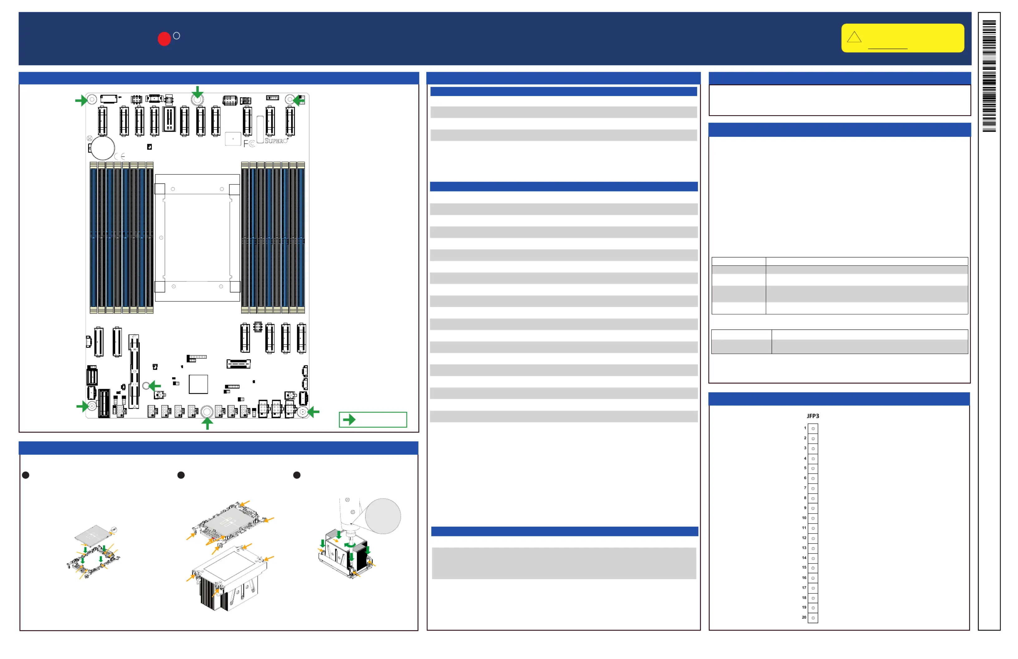
Motherboard Layout and Features
Download Drivers and Utilities: https://www.supermicro.com/wdl/driver/
Refer to the Component Installation section of the user manual for information on jumpers, connectors, LED Indicators, memory support, and processor installation instructions.
Processor Support
The motherboard supports up to 4 TB of DDR5 RDIMM/3DS RDIMM with speeds of up to
6400 MT/s (1DPC) and 5200 MT/s (2DPC) in 32 GB, 64 GB, 96 GB, 128 GB, and 256 GB
RDIMM/3DS RDIMM sizes.
The motherboard supports up to 512 GB of DDR5 MRDIMM-8800 with speeds of up to 8000
MT/s in 32 GB and 64 GB MRDIMM-880 sizes.
•It is recommended to use DDR5 memory of the same type, size, and speed.
•Mixed DIMM speeds can be installed. However, all DIMMs will run at the speed of the
slowest DIMM.
•The motherboard will support an odd number amount of memory modules. However, to
achieve the best memory performance, a balanced memory population is recommended.
The X14SBGM motherboard supports the Intel
®
Xeon
®
6700-series processors with rich P-cores
in Socket E2 LGA 4710 with a Thermal Design Power (TDP) of up to 350 W.
ConnectorDescription
BT1CMOS Battery
CN4I/O Module Connector
FAN1–FAN8Fan Headers
J35, J36Liquid Cooling Leakage Sensor Connectors
JBMC1External BMC Module Connector
JBOOT (P1_PE1 4–7)M.2 Boot Tray Connector for AOM-DCM2-BOOT
JCPLD1CPLD Connector
JFP3Front Control Panel Header
JL1Chassis Intrusion Header
JNCSI1NC-SI Connection
JNVI
2
C1NVMe Backplane I
2
C Connector
JNVVPP1NVMe VPP Header
JPDB1Power Distributor Board Sideband Signal Header
JPWR1–JPWR38-pin +12 V GPU MICRO-HI Power Connectors
JPWR52-pin +12 V Standby Input from PSU
JPWR62-pin +12 V Standby Output to I/O Module (AOM-IO-GP102)
JRK1VROC Raid Key Header
JRSI
2
C1Fan Board Control Header
JTPM1Trusted Platform Module/Port 80 Connector
MCIO 0A, MCIO 0B, MCIO
2A, MCIO 2B, MCIO 3A,
MCIO 3B, MCIO 4A, MCIO
4B, MCIO 5A, MCIO 5B,
MCIO 6A, MCIO 6B, MCIO
7A, MCIO 7B, MCIO 8A,
MCIO 8B
MCIO PCIe 5.0 p1-x8 Connectors
LEDDescriptionStatus
LE6Power Regulator LED
Green: Power Ready
Amber: Standby
Red: Power Failure
LED2Onboard Power LED
Off: System Off
Green: System On
Power Button
Storage Drive Activity LED
GND
GND
P5V_USB
I2C Clock
Fail LED_N (OH/FF/PF)
GND
Reset/UID Button
P3V3_STBY
Power Fail LED_N
Standby LED_N
Power Fail LED_P
LAN-1 Activity LED (Aggregate all LAN)
I2C Data
UID LED_N
LAN-2 Activity LED
Power/RoT LED_N
P5V_USB
P5V_USB
LED Indicators
Jumpers
Connectors
JumperDescriptionDefault Setting
JBT1CMOS ClearOpen (Normal)
JI
3
CSW1I³C Functionality JumperPins 1–2 (I³C)
JLC1Cooling Select JumperPins 1–2 (Air Cool)
JRU1UID/Reset Button Select JumperPins 1–2 (UID)
= mounting hole
Front Control Panel (JFP3)
Processor and PHM Installation
Number of DIMMsMemory Population Sequence (RDIMM/3DS RDIMM)
1 (Recommended)DIMMA1
4
DIMMA1/DIMMC1/DIMME1/DIMMG1
DIMMB1/DIMMD1/DIMMF1/DIMMH1
8
DIMMA1/DIMMB1/DIMMC1/DIMMD1/DIMME1/DIMMF1/DIMMG1/DIMMH1
DIMMA1/DIMMA2/DIMMC1/DIMMC2/DIMME1/DIMME2/DIMMG1/DIMMG2
DIMMB1/DIMMB2/DIMMD1/DIMMD2/DIMMF1/DIMMF2/DIMMH1/DIMMH2 (Recommended)
16 (Recommended)
DIMMA1/DIMMA2/DIMMB1/DIMMB2/DIMMC1/DIMMC2/DIMMD1/DIMMD2/DIMME1/DIMME2/
DIMMF1/DIMMF2/DIMMG1/DIMMG2/DIMMH1/DIMMH2
Number of DIMMsMemory Population Sequence (MRDIMM)
8
DIMMA1/DIMMB1/DIMMC1/DIMMD1/DIMME1/DIMMF1/DIMMG1/DIMMH1
1
1
1
2
1
3
Assemble the processor carrier assembly by aligning and
placing one end of the processor into the latch marked A, and
place the other end of processor into the latch marked B.
To form the processor heatsink module (PHM),
mount the processor carrier assembly onto the
heatsink and snap into place.
After assembling the PHM, mount it onto the
processor socket. With a T30 bit torque driver
set to a force of 8.0 in-lbf (0.904 N-m), gradually
tighten the four screws.
The processor carriers (SKT-1543H-0000-FXC
and SKT-1544H-0000-FXC) are included in the
shipping package.
a
c
b
d
C
D
B
Pin 1
A
Latch
Latch
Processor Key b
Processor Key a
Processor Key A
Processor Key B
Latch
Latch
3
4
5
6
7
8
9
1
0
1
1
lbf-in
8.0
0.904
N-m
D
B
A
C
Produktspezifikationen
| Marke: | Supermicro |
| Kategorie: | Nicht kategorisiert |
| Modell: | X14SBGM |
Brauchst du Hilfe?
Wenn Sie Hilfe mit Supermicro X14SBGM benötigen, stellen Sie unten eine Frage und andere Benutzer werden Ihnen antworten
Bedienungsanleitung Nicht kategorisiert Supermicro

3 April 2026
16 März 2026
6 Februar 2026
22 Januar 2026
22 Januar 2026
21 Januar 2026
18 Januar 2026
17 Januar 2026
14 Januar 2026
9 Oktober 2025
Bedienungsanleitung Nicht kategorisiert
Neueste Bedienungsanleitung für -Kategorien-
3 April 2026
3 April 2026
3 April 2026
3 April 2026
3 April 2026
3 April 2026
3 April 2026
3 April 2026
3 April 2026
3 April 2026