Tennsco 1470 Bedienungsanleitung


Lies die bedienungsanleitung für Tennsco 1470 (4 Seiten) kostenlos online; sie gehört zur Kategorie Schrank. Dieses Handbuch wurde von 2 Personen als hilfreich bewertet und erhielt im Schnitt 4.9 Sterne aus 1.5 Bewertungen. Hast du eine Frage zu Tennsco 1470 oder möchtest du andere Nutzer dieses Produkts befragen? Stelle eine Frage

Seite 1/4
RETAIN INSTRUCTIONS FOR FUTURE REFERENCE!
PK-1730212
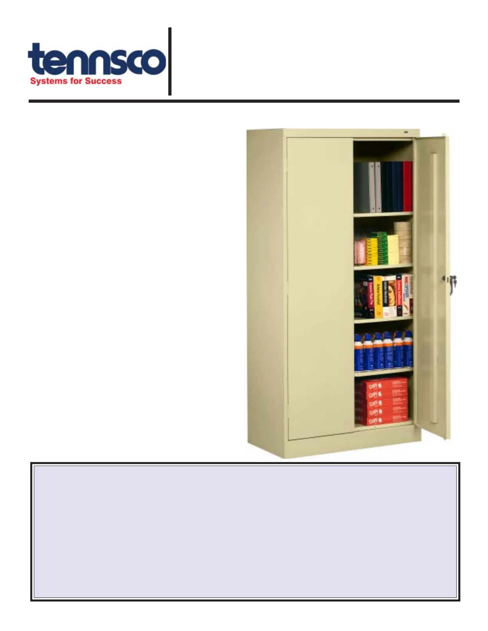
Congratulations on your purchase of a
Tennsco Storage Cabinet! Tennsco's 1470
units are general purpose storage cabinets
that provide a level of quality you won't find
elsewhere. They provide secure storage for
office supplies, books, records, small parts,
tools, etc.
adjustable shelves, a locking chrome handle
with two keys, and a three-point locking
system for extra security.
Tennsco's cabinets are constructed from top
steel shelves offering weight capacities of up
to 200 lbs. per shelf (evenly distributed). Our
attractive and durable powder-coated paint
finish will provide for years of service.
GENERAL SAFETY INFORMATION
Some parts may have sharp edges. CARE must
be taken when handling various pieces to avoid
injury. For safety, wear a pair of work gloves when
assembling or performing any maintenance on
your cabinet.
ASSEMBLY INSTRUCTIONS & PARTS MANUAL #1730212
Tennsco Corp., Dickson, TN 37056-1888 • (615) 446-8000
TENNSCO STORAGE CABINET
Model 1470
LIMITED WARRANTY
Tennsco warrants goods purchased hereunder to be free of defects in materials and workmanship for a period of one (1) year from the date of shipment, hereunder.
This warranty shall not apply in the event goods are damaged as a result of misuse, abuse, neglect, accident, improper application, modification or repair by persons
not authorized by Seller, where goods are damaged during shipment, or where the date stamps on the goods have been defaced, modified or removed. UNLESS
CONSIDERED UNENFORCEABLE OR UNLAWFUL UNDER APPLICABLE LAW:
a. ALL IMPLIED WARRANTIES, INCLUDING BUT NOT LIMITED TO WARRANTIES OR MERCHANTABILITY AND FITNESS FOR A PARTICULAR
PURPOSE ARE HEREBY EXCLUDED:
b. BUYERS REMEDY, IF ANY, FOR ANY DEFECTIVE GOODS SHALL BE LIMITED TO A REFUND BY SELLER OR REPLACEMENT OF THE GOODS
AT SELLER’S OPTION, AND SHALL IN NO EVENT INCLUDE DAMAGES OF ANY KIND, WHETHER INCIDENTAL, CONSEQUENTIAL OR
OTHERWISE.
NO GOODS ACCEPTED FOR RETURN WITHOUT PRIOR APPROVAL. Seller shall have the right to inspect any goods claimed to be defective at Buyers place
of business or require Buyer to return the goods to Seller for inspection on Seller’s premises. Transportation charges covering returned goods will be borne by
Seller only if such goods are proven to be defective, are covered by this warranty and are returned within the warranty period stated above.
TENNSCO Corp., P.O. BOX 1888, DICKSON, TN 37056-1888
(615) 446-8000 or (866) 446-8686 (toll free)
Website: www.tennsco.com E-mail: Info@tennsco.com
Tools Needed: A free
11
/32" nut driver is provided with each Tennsco cabinet (Ref. No. 17). In addition,
you will need a flathead screwdriver. A hammer is required to install the hinge pin and lock bar.
Two people recommended for installation. Approximate assembly time: 15 to 25 minutes.
INSTALLATION OF 1470 CABINETS
1. The reference numbers used throughout this
sheet refer to the illustration on the back cover.
This is to help you to identify the various parts as
they are mentioned.
2. Place the cabinet back (Ref. No. 1) on a
protected surface to prevent
scratching the paint. The
flange on the
bottom of
the back
should be facing
upward.
4. Attach the right side (Ref. No. 3) to the back in the
same manner as you did in step 3, again making
sure that the flange is
around the back and that
the lances on the shelf
adjustment strips are
pointed in the
same di-
tion as
those on
the back and
left side.
6. Insert bolts into the outside
holes on the header (Ref. No.
5), placing two on each end
as shown in Inset A. Attach
the nuts, but do not tighten. Next, insert
the loose bolt heads on the
header into the large
end of the
keyhole
slots
at the
top of
each
side panel.
Slide the bolt
heads securely into the smaller end
of the keyhole slot, and tighten the
four nuts securely.
7. Attach the sill (Ref. No. 6) to the two holes on
each side of the cabinet bottom, using the same
technique you used to attach
the header in step 6.
Flange faces upward
3. Attach the left side (Ref. No. 2) to the back by
placing flange (A) around the back and
bolting the back and
side together with
seven
bolts
and
nuts
(Ref.
Nos. 18 & 19).
Be sure that
the lances on
all shelf adjustment
strips (B) point in the same direction.
Flange goes
under back
B
A
5. To help hold the sides in position, insert one
shelf (Ref. No. 4) into the approximate center of
the unit, inserting the shelf edges into the lances
on all four shelf adjust- ment strips.
Be sure that the
channeled edge of
the shelf is toward
the cabinet
front. If
a lance
is too
tight, it
may be
helpful to use
a screwdriver to
SLIGHTLY pry it open.
Two bolts
and nuts on
each side
All lances point UP
on both back
and side.
Inset A
Inset B
Loosely place
two bolts and
nuts on each
side, then
slide into
keyhole slots
and secure.
Inset A
Place bolt heads into
keyhole slots, slide to
narrow end, and
secure nuts.
8. Place bottom (Ref. No. 7) in the bottom
lances of
the shelf adjustment strips.
The
flange
with two
holes
should
face the
front,
and it
should hang
over the sill.
Bolt to the sill with two bolts and nuts.
9. Attach the top (Ref. No. 8) by sliding it
under the header and sides, with the
flange hanging over
the back.
Secure with 14 bolts &
nuts (three
along
each
side,
four in
the back,
and four
along the front).
11. Attach the
left door
(Ref. No. 9) to the unit by
placing the door on the hinges,
aligning the holes,
and using a
hammer
to tap the hinge pins
(Ref. No. 16) into place
with
the side of a screwdriver.
10. Set the unit upright and insert
the remaining shelves at
your desired levels.
Insert shelf into
bottom lances.
Two holes must
be in front.
12. Attach the right door
(Ref. No. 10) to the unit
in the same way you
attached the left door.
1. Place the locking handle
(Ref. No. 12) on the
right hand door and
fasten with two #8-32 x
1/4" slotted hex-head
bolts and lockwashers
(Ref. No. 17).
Handle/Locking System Installation Instructions
4. Slide the nylon lock bar
guide inserts (Ref. No. 15)
over the lock bar ends and
through the door slots (see
"B" at right). Push firmly
until the guides snap into
place. If necessary, turn
the handle back to the
open position and gently
tap with a hammer until the
guides slide into place.
A
B
B
2. Turn the handle to
the open position, and
place the locking cam
(Ref. No. 13) over the square
shank of the door handle. The
latch must be facing down-
ward as shown. Then place the
locking cotter pin (Ref. No. 14)
through the hole of
the square shank,
as shown at right.
3. With the handle still in the open
position, hook the locking bars (Ref.
No. 11) to the locking cam (see "A" at
left). Once in position, slowly rotate the
door handle to the closed position so
the lock bars protrude from the holes
at the top and bottom of the door
(shown at right, below).


Produktspezifikationen

Marke: Tennsco
Kategorie: Schrank
Modell: 1470

Brauchst du Hilfe?

Wenn Sie Hilfe mit Tennsco 1470 benötigen, stellen Sie unten eine Frage und andere Benutzer werden Ihnen antworten