TOA RM-300X Bedienungsanleitung


Lies die bedienungsanleitung für TOA RM-300X (77 Seiten) kostenlos online; sie gehört zur Kategorie Nicht kategorisiert. Dieses Handbuch wurde von 19 Personen als hilfreich bewertet und erhielt im Schnitt 4.8 Sterne aus 10 Bewertungen. Hast du eine Frage zu TOA RM-300X oder möchtest du andere Nutzer dieses Produkts befragen? Stelle eine Frage

Seite 1/77
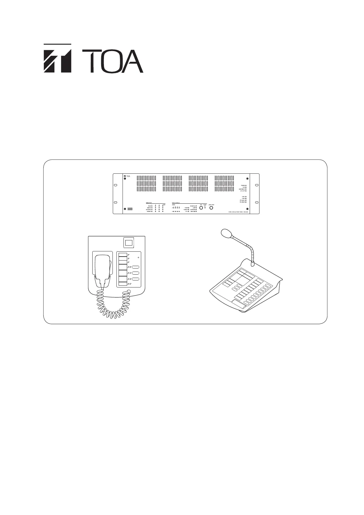
OPERATING INSTRUCTIONS
INTEGRATEd VOICE EVACUATION SYSTEM
VX-3000 SERIES
RM-200SF
VX-3004F
RM-300X
Thank you for purchasing TOA's Integrated Voice Evacuation System.
Please carefully follow the instructions in this manual to ensure long, trouble-free use of your equipment.
2
TABLE OF CONTENTS
Chapter 1 : NOMENCLATURE
1. VX-3004F, VX-3008F, ANd VX-3016F
VOICE EVACUATION FRAME ............................................................... 1-2
2. RM-200SF FIREMAN’S MICROPHONE
ANd RM-320F REMOTE MICROPHONE EXTENSION ........ 1-5
2.1. RM-200SF .......................................................................................................... 1-5
2.2. RM-320F ............................................................................................................ 1-7
3. RM-300X REMOTE MICROPHONE ANd
RM-210F REMOTE MICROPHONE EXTENSION
..................... 1-8
3.1. RM-300X ............................................................................................................ 1-8
3.2. RM-210F ............................................................................................................ 1-9
Chapter 2 : INdICATOR STATUS OF REMOTE MICROPHONES
1. RM-200SF FIREMAN’S MICROPHONE ANd
RM-320F REMOTE MICROPHONE EXTENSION
..................... 2-2
1.1. Indicator State at the Time of Zone Selection .................................................... 2-2
1.2. Talk Key Indicators ............................................................................................ 2-3
1.3. Indicator State at the Time of Base Pattern Change ........................................ 2-4
1.4. Indicator State at the Time of General-Purpose Broadcast Pattern ................. 2-4
1.5. Indicator State at the Time of General/BGM Broadcast ................................... 2-5
1.6. Indicator State at the Time of RM Broadcast Status Display ............................ 2-5
1.7. Indicator State at the Time of Lamp Test ........................................................... 2-6
1.8. Indicator State at the Time of Failure Output Receipt ........................................ 2-7
1.9. Indicator State at the Time of Failure Output Reset .......................................... 2-8
1.10. Indicator State at the Time of Emergency Broadcast Pattern Start ................ 2-9
1.11. Indicator State at the Time of Emergency Broadcast Pattern Stop ................ 2-10
1.12. Indicator State at the Time of Emergency Broadcast Pattern Start/Stop ....... 2-11
1.13. Indicator State at the Time of Emergency Sequence Stop ............................ 2-12
1.14. Indicator State at the Time of Emergency Sequence Phase Shift ................. 2-13
1.15. Indicator State at the Time of Emergency Reset ............................................ 2-14
1.16. Indicator State at the Time of Audio Monitor .................................................. 2-15
1.17. Indicator State at the Time of Intended Control Input ..................................... 2-15
1.18. Indicator State at the Time of Intended Control Output (Pulse) ...................... 2-16
1.19. Indicator State at the Time of Intended Control Output (Level) ...................... 2-16
1.20. Indicator State at the Time of Zone Volume Adjustment (Pulse) ................... 2-17
1.21. Indicator State at the Time of Input Volume Adjustment (Pulse) .................... 2-18
1.22. Indicator State at the Time of Emergency Warning Broadcast ...................... 2-19
2. RM-300X REMOTE MICROPHONE ANd
RM-210F REMOTE MICROPHONE EXTENSION
................... 2-20
2.1. Indicator State at the Time of Zone Selection .................................................. 2-20
2.2. Talk Key Indicators ........................................................................................... 2-21
2.3. Indicator State at the Time of Base Pattern Change ....................................... 2-21
2.4. Indicator State at the Time of General-Purpose Broadcast Pattern ................ 2-22
3
2.5. Indicator State at the Time of General/BGM Broadcast .................................. 2-22
2.6. Indicator State at the Time of RM Broadcast Status Display ........................... 2-23
2.7. Indicator State at the Time of Lamp Test ......................................................... 2-23
2.8. Indicator State at the Time of Failure Output Receipt ...................................... 2-24
2.9. Indicator State at the Time of Failure Output Reset ......................................... 2-25
2.10. Indicator State at the Time of Emergency Broadcast Pattern Start ............... 2-26
2.11. Indicator State at the Time of Emergency Broadcast Pattern Stop ................ 2-27
2.12. Indicator State at the Time of Emergency Broadcast Pattern Start/Stop ....... 2-28
2.13. Indicator State at the Time of Emergency Sequence Stop ............................ 2-29
2.14. Indicator State at the Time of Emergency Sequence Phase Shift ................ 2-30
2.15. Indicator State at the Time of Emergency Reset ............................................ 2-31
2.16. Indicator State at the Time of Audio Monitor ................................................. 2-32
2.17. Indicator State at the Time of Intended Control Input .................................... 2-32
2.18. Indicator State at the Time of Intended Control Output (Pulse) .................... 2-33
2.19. Indicator State at the Time of Intended Control Output (Level) ..................... 2-33
2.20. Indicator State at the Time of Zone Volume Adjustment (Pulse) .................. 2-34
2.21. Indicator State at the Time of Input Volume Adjustment (Pulse) ................... 2-35
2.22. Indicator State at the Time of Emergency Warning Broadcast ..................... 2-36
Chapter 3 : OPERATION
1. BGM ANd GENERAL BROAdCAST ................................................ 3-2
1.1. Broadcasting from the RM-200SF, RM-300X, RM-320F, and RM-210F ........... 3-2
1.2. Assignment Example ........................................................................................ 3-2
1.3. Operation Examples ......................................................................................... 3-3
2. EMERGENCY wARNING BROAdCAST ....................................... 3-9
3. EMERGENCY BROAdCAST ................................................................ 3-10
3.1. Typical System Examples ................................................................................ 3-10
3.2. Remote Microphone Operation Example ........................................................ 3-12
4. MAkING ALL-ZONE EMERGENCY BROAdCAST ................ 3-15
4.1. Priority Control of the All-Zone Emergency Broadcast ..................................... 3-15
4.2. Making All-zone Emergency Broadcast from the RM-300X ............................ 3-16
4.3. Making All-zone Emergency Broadcast from the RM-200SF .......................... 3-17
5. dETECTING FAULT ................................................................................... 3-18
5.1. Fault Detection Setting Example ...................................................................... 3-18
5.2. Case Example of Malfunction .......................................................................... 3-19
5.3. Remote Microphone's Operation Example ..................................................... 3-20
5.4. VX-3004F's Operation Example ...................................................................... 3-21
5.5. Example of Executing the Failure Reception and Failure Reset
by Way of the Control Input Terminals ............................................................ 3-22
6. LAMP TEST .................................................................................................... 3-23
6.1. Remote Microphone's Operation Example ...................................................... 3-23
6.2. VX-3004F's Operation Example ...................................................................... 3-24
7. OTHER FUNCTIONS ................................................................................. 3-25
7.1. Audio Monitor ................................................................................................... 3-25
7.2. Intended Control Input Operation .................................................................... 3-26


Produktspezifikationen

Marke: TOA
Kategorie: Nicht kategorisiert
Modell: RM-300X

Brauchst du Hilfe?

Wenn Sie Hilfe mit TOA RM-300X benötigen, stellen Sie unten eine Frage und andere Benutzer werden Ihnen antworten