Valcom VIP-142 Bedienungsanleitung
Valcom Lautsprecher VIP-142
Lies die bedienungsanleitung für Valcom VIP-142 (5 Seiten) kostenlos online; sie gehört zur Kategorie Lautsprecher. Dieses Handbuch wurde von 24 Personen als hilfreich bewertet und erhielt im Schnitt 4.1 Sterne aus 3 Bewertungen. Hast du eine Frage zu Valcom VIP-142 oder möchtest du andere Nutzer dieses Produkts befragen? Stelle eine Frage
Seite 1/5
Issue 1
1 947103
CAUTION: To reduce the risk of electric shock,
Do not remove cover (or back).
No user serviceable parts inside.
Refer servicing to qualified service personnel.
CAUTION
RISK OF ELECTRIC SHOCK
DO NOT OPEN
This symbol indicates that dangerous
voltage constituting a risk of electric
shock is present within this unit.
This symbol indicates that there are
important operating and maintenance
instructions in the literature accompanying
this unit.
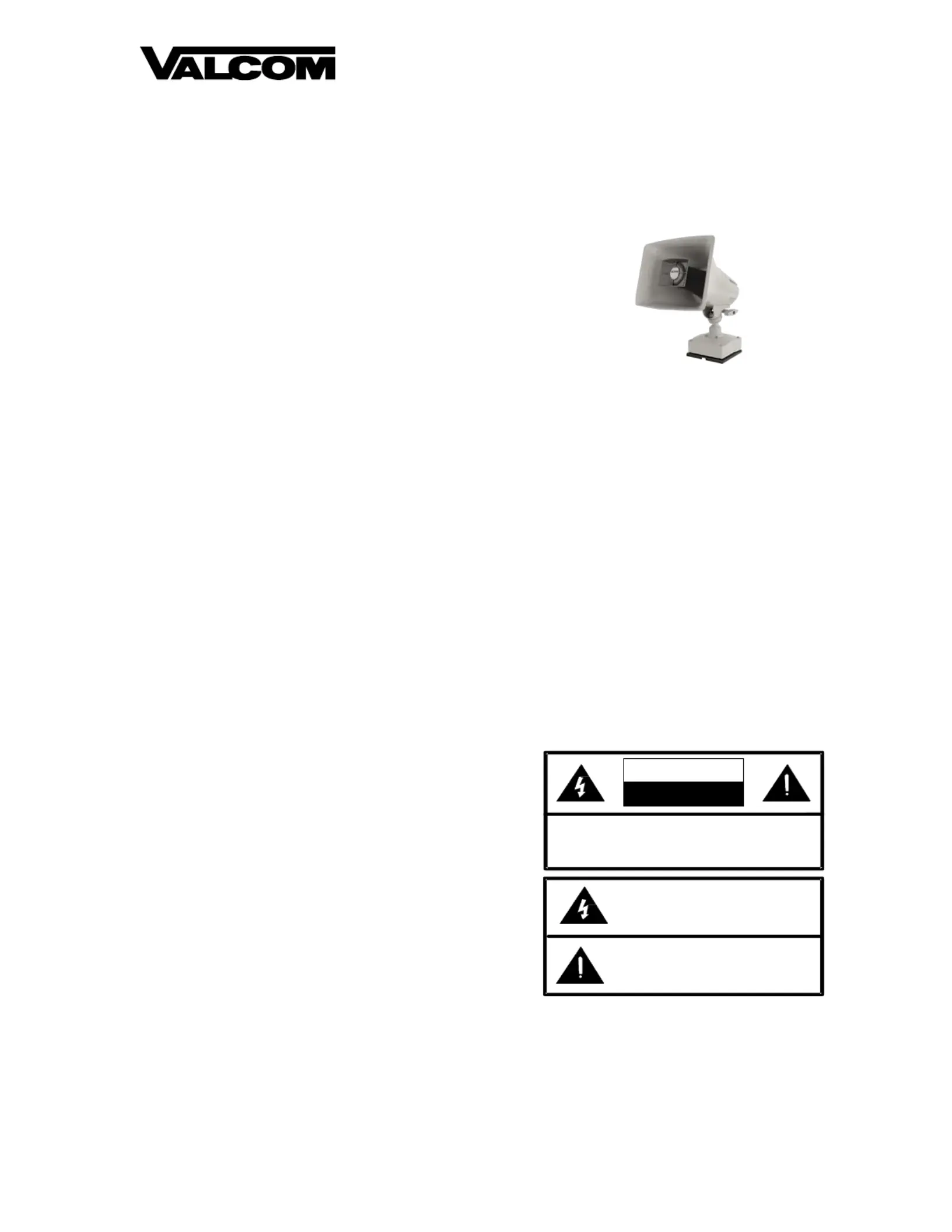
VIP-142
High Power Paging ornIP Talkback H
INTRODUCTION
The VIPHorn is a weather-142 PagingIP -
resistant, high-efficiency horn supporting
multiple audio and control protocols, all
delivered via a PoEenabled IP network. A -
separate microphone facilitates full-duplex
talkback cThe highommunication. -impact
Polycarbonate construction resists the
deteriorating effects of outdoor installation.
SPECIFICATIONS
Access Methods
•SIP telephone system
• Valcom M Cast Page Group
•-A PBX, FXO Port w/VIP811
•P-A OTS telephone set w/VIP811
•-A PBX, FXS Port w/VIP821
Features
• Indoor/ Outdoor use
• High Impact carbonate HousingPoly
•- OmniDirectional Mounting Base
•- Builtin Microphone
•d SIP & Multicast Enable
•Power over Ethernet (PoE) 802.3af and
802.3at mpatibl(PoE+) coe
•R emote Management & Monitoring
D/ Wt imensions eigh
•” 11.75H x 10.0” Wx 11.0” D(29.8cm H x
25.4cm W x 27.9cm D)
• 4.3 lbs. (1.95 kg)
Audio Codecs
•LL G.722, G.711 (uaw, aaw)
Frequency Response
•z 350 Hz to 7kH
Audio Dispersion
•l 120° Horizonta
• 90° Vertical
Nominal Power Requirements
IEEE PoE) 802.3af ( Class 3
IEEE 802.3at (PoE+) Class 4
These products are intended for use with a UL
Listed power source marked “Class 2” or “LPS”
ratedcdc(PoEd 24 V, or 48 V ).
PoE and all interconnected ITE are intended for
intra-. building
Environment
Temperature: - 20° 0 to +5° C
Humidity:0 ond - 95% non-censing
Produktspezifikationen
| Marke: | Valcom |
| Kategorie: | Lautsprecher |
| Modell: | VIP-142 |
Brauchst du Hilfe?
Wenn Sie Hilfe mit Valcom VIP-142 benötigen, stellen Sie unten eine Frage und andere Benutzer werden Ihnen antworten
Bedienungsanleitung Lautsprecher Valcom

31 März 2026
27 März 2026
22 März 2026
19 März 2026
4 März 2026
29 November 2025
25 November 2025
8 Oktober 2025
25 September 2025
1 August 2025
Bedienungsanleitung Lautsprecher
Neueste Bedienungsanleitung für -Kategorien-
3 April 2026
3 April 2026
3 April 2026
3 April 2026
2 April 2026
2 April 2026
2 April 2026
2 April 2026
2 April 2026
2 April 2026