Valcom VIP-824A Bedienungsanleitung
Valcom Türsprechanlage VIP-824A
Lies die bedienungsanleitung für Valcom VIP-824A (4 Seiten) kostenlos online; sie gehört zur Kategorie Türsprechanlage. Dieses Handbuch wurde von 11 Personen als hilfreich bewertet und erhielt im Schnitt 4.8 Sterne aus 7 Bewertungen. Hast du eine Frage zu Valcom VIP-824A oder möchtest du andere Nutzer dieses Produkts befragen? Stelle eine Frage
Seite 1/4
1 947494
ISSUE 2
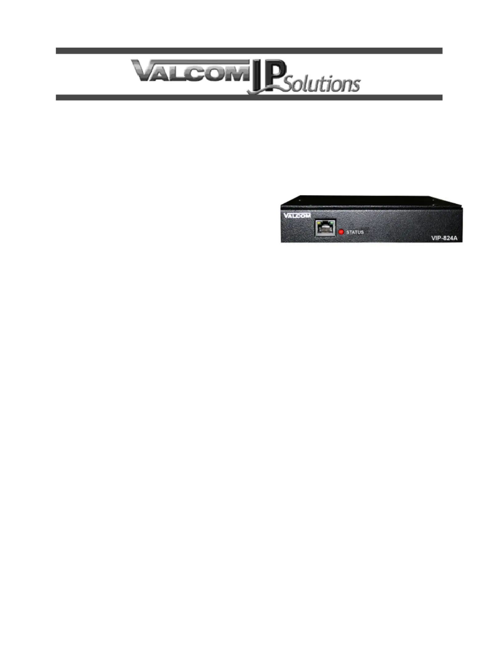
VIP-A 824
QUAD ENHANCED NETWORKED TRUNK PORT
INTRODUCTION
The VIPNetworked Trunk -824Quad Enhanced A
Port allows most loop start station ports to be
connected to a managed IPbased LAN/WAN. -
SIP -A connectivity allows the VIP824to act as a
gateway device between a SIP telephone system
and the other Valcom paging systems, such as the
MultiPath.
SPECIFICATIONS
Access Methods
• PBX, FXS Port
• SIP
Features
•- RJ45 for network connection
•- 4 RJ11 FXO connections
•- 4 RJ11 failover telephone connections
• Decode Caller ID signals
• Front panel activity LED
•Network activity LEDs
• 2.5mm jack for DC power
• Power over Ethernet (PoE) 802.3af compatible
Dimensions/Weight
• 5.2 1.38H x 6.13" W x 5" D
(30.5cm H x 15.6.3 cm W x 133cm D)
•2 Weight: 1.5 lbs. (0.57kg)
Nominal Specifications
Input Impedance:600 Ohms
Input Level: -10dBm
Output Impedance:600 Ohms
Output Level: - 10dBm nominal
Nominal Power Requirements
Via back panel barrel connector:
Voltage: 24VDC
Current:325mA
Via 802.3af PoE Ethernet Switch:
802.3af: Class 3
Environment
Temperature: 0 to +40° C
Humidity: 0 to 85% non - precipitating
INSTALLATION
NOTE: The telephone system referred to in this
manual is the customer premise equipment
such as an electronic key system, a PBX or a
dedicated single line telephone sets. The
VIP-A 824is not intended for direct or indirect
connection to the public telephone network.
When used with a customer premise telephone
system such as a key system or PBX system,
these units are interfaced to the system via a
fully protected system central office port,
which is a fully protected interface device.
Also, the host system must be configured to
disallow central office trunk conferencing in
order to prevent indirect connection to the
public network.
Produktspezifikationen
| Marke: | Valcom |
| Kategorie: | Türsprechanlage |
| Modell: | VIP-824A |
Brauchst du Hilfe?
Wenn Sie Hilfe mit Valcom VIP-824A benötigen, stellen Sie unten eine Frage und andere Benutzer werden Ihnen antworten
Bedienungsanleitung Türsprechanlage Valcom

14 März 2026
12 Februar 2026
9 Februar 2026
9 Februar 2026
8 Februar 2026
7 Februar 2026
7 Februar 2026
7 Februar 2026
6 Februar 2026
5 Februar 2026
Bedienungsanleitung Türsprechanlage
Neueste Bedienungsanleitung für -Kategorien-
17 März 2026
9 März 2026
4 März 2026
4 März 2026
27 Februar 2026
28 Januar 2026
13 Januar 2026
12 Januar 2026