Whirlpool GMF 7522/IXL Bedienungsanleitung
Lies die bedienungsanleitung für Whirlpool GMF 7522/IXL (4 Seiten) kostenlos online; sie gehört zur Kategorie Herd. Dieses Handbuch wurde von 2 Personen als hilfreich bewertet und erhielt im Schnitt 5.0 Sterne aus 1.5 Bewertungen. Hast du eine Frage zu Whirlpool GMF 7522/IXL oder möchtest du andere Nutzer dieses Produkts befragen? Stelle eine Frage
Seite 1/4
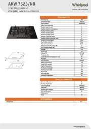
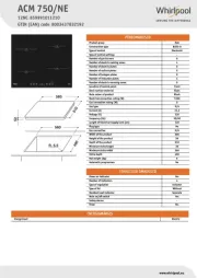
PRODUCT DESCRIPTION SHEET
PRODUCT DESCRIPTION SHEET
PRODUCT DESCRIPTION SHEET
PRODUCT DESCRIPTION SHEETPRODUCT DESCRIPTION SHEET
EN
EN
EN
EN EN
5019 300 02568
5019 300 02568
5019 300 02568
5019 300 025685019 300 02568
AU
AU
AU
AUAU
T
T
T
TT
o get full satisfaction from the hob,
o get full satisfaction from the hob,
o get full satisfaction from the hob,
o get full satisfaction from the hob, o get full satisfaction from the hob, please read these instruct
please read these instruct
please read these instruct
please read these instructplease read these instructions carefully and keep them
ions carefully and keep them
ions carefully and keep them
ions carefully and keep themions carefully and keep them for future consultation.
for future consultation.
for future consultation.
for future consultation. for future consultation.
LIGHTING THE BU
LIGHTING THE BU
LIGHTING THE BU
LIGHTING THE BULIGHTING THE BURNERS
RNERS
RNERS
RNERSRNERS
• To ignite one of the burners, turn the relative knob anti-clockwise to the maximum flame setting .
• Press the knob against the control panel to ignite the burner.
• After the burner has ignited, keep the knob pressed for about 5 seconds to allow the thermocouple to warm up.
This burner safety device shuts off the gas supply to the burner if the flame goes out accidentally (because of sudden
draught, an interruption in the gas delivery, boiling over of liquids, etc.).
•
•
•
•• The device must not be pressed for more
The device must not be pressed for more
The device must not be pressed for more
The device must not be pressed for more The device must not be pressed for more than 15 sec. If
than 15 sec. If
than 15 sec. If
than 15 sec. Ifthan 15 sec. If, after that tim
, after that tim
, after that tim
, after that tim, after that time has el
e has el
e has el
e has ele has elapsed, the burner d
apsed, the burner d
apsed, the burner d
apsed, the burner dapsed, the burner does not remain lit,
oes not remain lit,
oes not remain lit,
oes not remain lit, oes not remain lit,
wait at least one minute befo
wait at least one minute befo
wait at least one minute befo
wait at least one minute befowait at least one minute before trying to light it again.
re trying to light it again.
re trying to light it again.
re trying to light it again.re trying to light it again.
- The burner might go out when the knob is released. This means that the thermocouple has not warmed up enough.
In this case, repeat the operations described above.
RACTICAL AD
RACTICAL AD
RACTICAL AD
RACTICAL ADRACTICAL ADVICE FOR USING THE BURNERS
VICE FOR USING THE BURNERS
VICE FOR USING THE BURNERS
VICE FOR USING THE BURNERSVICE FOR USING THE BURNERS
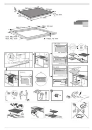
1. Removable panstand grids
2. Semi-rapid burner FC
3. Auxiliary burner
4. Semi-rapid burner BC
5. Rapid burner
6. 2 ring burner
7. Auxiliary burner control knob
8. Rapid burner control knob
9. 2 ring burner control knob
10. Semi-rapid burner FC control knob
11. Semi-rapid burner BC control knob
Symbols
Tap closed
Maximum flame
Minimum flame
32
78109
6
11
1 4 5
This hob has burners of different diameters. For better burner performance,
please stick to the following rules:
- Use pots and pans with bottoms the same width as that of the burners or
slightly larger (see table on the right).
- Only use flat-bottomed pots and pans.
- Use the correct amount of water for cooking foods and keep the pot covered.
- Make sure pots on the grates do not protrude beyond the edge of the hob
- In the case of pans with convex bottoms (WOK), use the support grille
(not included), which should be positioned only on the 2 ring burner.
IMPORTANT: improper use of the grids can result in damage to the hob: do
IMPORTANT: improper use of the grids can result in damage to the hob: do
IMPORTANT: improper use of the grids can result in damage to the hob: do
IMPORTANT: improper use of the grids can result in damage to the hob: do IMPORTANT: improper use of the grids can result in damage to the hob: do
not position the grids upside down o
not position the grids upside down o
not position the grids upside down o
not position the grids upside down onot position the grids upside down or slide them across the hob.
r slide them across the hob.
r slide them across the hob.
r slide them across the hob.r slide them across the hob.
Do not use:
Do not use:
Do not use:
Do not use:Do not use:
- Cast iron griddles, ollar stones, terracotta pots and pans.
- Heat diffusers such as metal mesh, or any other types.
- Two burners simultaneously for one receptacle (e.g. fish kettle).
Burner
Burner
Burner
BurnerBurner P
P
P
PPot Ø
ot Ø
ot Ø
ot Øot Ø
2 ring From 24 to 30 cm
Rapid From 24 to 26 cm
Semi-rapid BC From 16 to 24 cm
Semi-rapid FC From 16 to 22 cm
Auxiliary From 8 to 14 cm
BC: means Back
Centre
FC: means Front
Centre
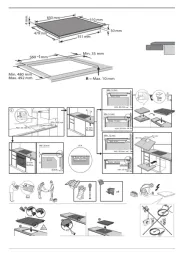
DIMENSIONS AND DIST
DIMENSIONS AND DIST
DIMENSIONS AND DIST
DIMENSIONS AND DISTDIMENSIONS AND DISTANCES
ANCES
ANCES
ANCES ANCES TO BE MAINT
TO BE MAINT
TO BE MAINT
TO BE MAINTTO BE MAINTAINED (mm)
AINED (mm)
AINED (mm)
AINED (mm)AINED (mm)
NOTE:
NOTE:
NOTE:
NOTE: NOTE: In case of installation of a hood
In case of installation of a hood
In case of installation of a hood
In case of installation of a hoodIn case of installation of a hood above the cooktop, please refer to
above the cooktop, please refer to
above the cooktop, please refer to
above the cooktop, please refer to above the cooktop, please refer to the ho
the ho
the ho
the ho the hood instructions for the correct distance.
od instructions for the correct distance.
od instructions for the correct distance.
od instructions for the correct distance.od instructions for the correct distance.
NOTE:
NOTE:
NOTE:
NOTE:NOTE: The indicated clearance dimensions are
The indicated clearance dimensions are
The indicated clearance dimensions are
The indicated clearance dimensions are The indicated clearance dimensions are applicable to al
applicable to al
applicable to al
applicable to alapplicable to all non-
l non-
l non-
l non-l non-combustible materials.
combustible materials.
combustible materials.
combustible materials.combustible materials.
ELECTRIC SUPPL
ELECTRIC SUPPL
ELECTRIC SUPPL
ELECTRIC SUPPLELECTRIC SUPPLY
Y
Y
YY: 220-240 V ~ 50/60 Hz 0.6 V
: 220-240 V ~ 50/60 Hz 0.6 V
: 220-240 V ~ 50/60 Hz 0.6 V
: 220-240 V ~ 50/60 Hz 0.6 V: 220-240 V ~ 50/60 Hz 0.6 VA
A
A
AA
WOK AD
WOK AD
WOK AD
WOK ADWOK ADAPTER
APTER
APTER
APTERAPTER
Gas T
Gas T
Gas T
Gas TGas T
ype
ype
ype
ypeype
Natural @ 1.00 kPa
(test point pressure)
Universal LP @ 2.75 kPa
(inlet pressure)
BURNER
BURNER
BURNER
BURNERBURNER
Nominal Gas
Consumption (MJ/h)
Nominal Injector Size
(mm)
Nominal Gas
Consumption (MJ/h)
Nominal Injector Size
(mm)
FRONT RHS Auxiliary 4.1 0.90 3.4 0.52
REAR CHS Semi-Rapid C 6.8 1.17 5.5 0.67
FRONT CHS Semi-Rapid C 6.8 1.17 5.5 0.67
REAR RHS Rapid 9.6 1.40 9.5 0.85
MIDDLE LHS Wok C 17.6 1.92 15.0 1.08
TOTAL 44.9 - 38.9 -
PRECAUTIONS AND GENERAL ADVICE
PRECAUTIONS AND GENERAL ADVICE
PRECAUTIONS AND GENERAL ADVICE
PRECAUTIONS AND GENERAL ADVICEPRECAUTIONS AND GENERAL ADVICE
T
T
T
TT
o get full satisfaction from your hob, please read these
o get full satisfaction from your hob, please read these
o get full satisfaction from your hob, please read these
o get full satisfaction from your hob, please read these o get full satisfaction from your hob, please read these instructions carefully and kee
instructions carefully and kee
instructions carefully and kee
instructions carefully and keeinstructions carefully and keep them for futur
p them for futur
p them for futur
p them for futurp them for future consultation
e consultation
e consultation
e consultatione consultation
• These instructions are only valid for those Countries where the destination abbreviations are mentioned on the product
description sheet and on the hob.
• Keep the packaging material (plastic bags, polystyrene parts, etc.) out of the reach of children, as they are potentially
dangerous.
• Check whether the hob has been damaged during transport and remove any protective film from the appliance parts.
•
•
•
•• This hob (Class 3) is designed solely
This hob (Class 3) is designed solely
This hob (Class 3) is designed solely
This hob (Class 3) is designed solely This hob (Class 3) is designed solely for household use for cooking food. Any other use (such as heating rooms
for household use for cooking food. Any other use (such as heating rooms
for household use for cooking food. Any other use (such as heating rooms
for household use for cooking food. Any other use (such as heating roomsfor household use for cooking food. Any other use (such as heating rooms) is to be
) is to be
) is to be
) is to be ) is to be
considered i
considered i
considered i
considered iconsidered improper and
mproper and
mproper and
mproper andmproper and, as
, as
, as
, as, as a consequence, dangerous.
a consequence, dangerous.
a consequence, dangerous.
a consequence, dangerous. a consequence, dangerous.
•
•
•
•• Ensure that the installation and gas/elec
Ensure that the installation and gas/elec
Ensure that the installation and gas/elec
Ensure that the installation and gas/elecEnsure that the installation and gas/electrical connections are perf
trical connections are perf
trical connections are perf
trical connections are perftrical connections are performed by a qualified technician in compliance with
ormed by a qualified technician in compliance with
ormed by a qualified technician in compliance with
ormed by a qualified technician in compliance with ormed by a qualified technician in compliance with
current local safety regulations
current local safety regulations
current local safety regulations
current local safety regulationscurrent local safety regulations.
.
.
..
•
•
•
•• This appliance should only be installe
This appliance should only be installe
This appliance should only be installe
This appliance should only be installeThis appliance should only be installed and
d and
d and
d and d and used in well-ventilated rooms, in
used in well-ventilated rooms, in
used in well-ventilated rooms, in
used in well-ventilated rooms, inused in well-ventilated rooms, in accordance with current regulations.
accordance with current regulations.
accordance with current regulations.
accordance with current regulations. accordance with current regulations.
Carefully read
Carefully read
Carefully read
Carefully readCarefully read the instructio
the instructio
the instructio
the instructio the instructions before
ns before
ns before
ns beforens before installing and using this appliance.
installing and using this appliance.
installing and using this appliance.
installing and using this appliance. installing and using this appliance.
•
•
•
•• Gas adjustment and supply pressure are
Gas adjustment and supply pressure are
Gas adjustment and supply pressure are
Gas adjustment and supply pressure are Gas adjustment and supply pressure are indicat
indicat
indicat
indicatindicated on the rating plate located under the hob. (Pl
ed on the rating plate located under the hob. (Pl
ed on the rating plate located under the hob. (Pl
ed on the rating plate located under the hob. (Pled on the rating plate located under the hob. (Pleas
eas
eas
easease,
e,
e,
e, e, ens
ens
ens
ensensure
ure
ure
ureure th
th
th
th the su
e su
e su
e sue suppl
ppl
ppl
pplpplie
ie
ie
ieied
d
d
d d
data label has to be attached in a suitable surf
data label has to be attached in a suitable surf
data label has to be attached in a suitable surf
data label has to be attached in a suitable surfdata label has to be attached in a suitable surface adjacent to the hotp
ace adjacent to the hotp
ace adjacent to the hotp
ace adjacent to the hotpace adjacent to the hotplate such as cupboard).
late such as cupboard).
late such as cupboard).
late such as cupboard). late such as cupboard).
If the appliance is arranged for a type of gas different from that available, refer
If the appliance is arranged for a type of gas different from that available, refer
If the appliance is arranged for a type of gas different from that available, refer
If the appliance is arranged for a type of gas different from that available, refer If the appliance is arranged for a type of gas different from that available, refer to the paragraph
to the paragraph
to the paragraph
to the paragraph to the paragraph “
“
“
““
Ajustment to different ty
Ajustment to different ty
Ajustment to different ty
Ajustment to different tyAjustment to different types
pes
pes
pes pes
of gas
of gas
of gas
of gasof gas”
”
”
””.
.
.
..
•
•
•
•• W
W
W
WWARNING: DO NOT SPRA
ARNING: DO NOT SPRA
ARNING: DO NOT SPRA
ARNING: DO NOT SPRAARNING: DO NOT SPRAY AEROSOLS IN
Y AEROSOLS IN
Y AEROSOLS IN
Y AEROSOLS INY AEROSOLS IN THE VICINITY OF THIS
THE VICINITY OF THIS
THE VICINITY OF THIS
THE VICINITY OF THIS THE VICINITY OF THIS APPLIANCE WHIL
APPLIANCE WHIL
APPLIANCE WHIL
APPLIANCE WHIL APPLIANCE WHILE IT IS IN OPERA
E IT IS IN OPERA
E IT IS IN OPERA
E IT IS IN OPERAE IT IS IN OPERATION.
TION.
TION.
TION.TION.
•
•
•
•• W
W
W
WWAR
AR
AR
ARARNING: ONL
NING: ONL
NING: ONL
NING: ONLNING: ONLY APPLIANCE WITH SAFETY DEVICE BURNERS CAN
Y APPLIANCE WITH SAFETY DEVICE BURNERS CAN
Y APPLIANCE WITH SAFETY DEVICE BURNERS CAN
Y APPLIANCE WITH SAFETY DEVICE BURNERS CANY APPLIANCE WITH SAFETY DEVICE BURNERS CAN BE INST
BE INST
BE INST
BE INST BE INSTALLED IN MARINE CR
ALLED IN MARINE CR
ALLED IN MARINE CR
ALLED IN MARINE CRALLED IN MARINE CRAFT OR
AFT OR
AFT OR
AFT OR AFT OR
CARA
CARA
CARA
CARACARAV
V
V
VVANS. IN ANY CASE, IT SHALL NOT BE USED AS A SP
ANS. IN ANY CASE, IT SHALL NOT BE USED AS A SP
ANS. IN ANY CASE, IT SHALL NOT BE USED AS A SP
ANS. IN ANY CASE, IT SHALL NOT BE USED AS A SPANS. IN ANY CASE, IT SHALL NOT BE USED AS A SPACE HEA
ACE HEA
ACE HEA
ACE HEAACE HEATER.
TER.
TER.
TER.TER.
•
•
•
•• W
W
W
WWARNING: DO NOT USE OR STORE FLAMMABLE MA
ARNING: DO NOT USE OR STORE FLAMMABLE MA
ARNING: DO NOT USE OR STORE FLAMMABLE MA
ARNING: DO NOT USE OR STORE FLAMMABLE MAARNING: DO NOT USE OR STORE FLAMMABLE MATERIALS IN THE APPLIANCE STORAGE DRA
TERIALS IN THE APPLIANCE STORAGE DRA
TERIALS IN THE APPLIANCE STORAGE DRA
TERIALS IN THE APPLIANCE STORAGE DRATERIALS IN THE APPLIANCE STORAGE DRAWER OR
WER OR
WER OR
WER OR WER OR
NEAR THIS APPLIANCE
NEAR THIS APPLIANCE
NEAR THIS APPLIANCE
NEAR THIS APPLIANCENEAR THIS APPLIANCE.
.
.
..
PROVISION F
PROVISION F
PROVISION F
PROVISION FPROVISION FO
O
O
OOR VENTILA
R VENTILA
R VENTILA
R VENTILAR VENTILATION
TION
TION
TIONTION
ROOM VENTILA
ROOM VENTILA
ROOM VENTILA
ROOM VENTILAROOM VENTILATION
TION
TION
TIONTION
To ensure correct operation of the appliance, the room size in which it is to be installed shall be in accordance with AS5601.
This room must also be continuously ventilated, fresh air should flow through permanent openings in walls to outside or to an
adjacent non-inhabitable room as detailed is AS 5601. These permanent openings must be made in such a way that it cannot
be obstructed from either side of the wall, also they should be protected by plastic grids, metallic mesh, etc., taking care not
to reduce the air vent effective area mentioned above and located near floor level and positioned so as not to interfere with
the operation of the exhaust system, the minimum cross section of these permanent openings is set by AS6501 and shown in
Fig 1a,1b and 1c.
OVERHEAD CLEARANCE
OVERHEAD CLEARANCE
OVERHEAD CLEARANCE
OVERHEAD CLEARANCEOVERHEAD CLEARANCE
Range hoods and exhaust fans shall be installed in accordance with the manufactures instructions. However, in no case shall
the clearance between the top of the highest burner of the cooking appliance and the range hood be less than 600 mm or, for
an overhead exhaust fan, 750 mm.
Any downward facing combustible surface less than 600 mm above the top of the highest burner shall be protected for the
full width and depth of the cooking surface area in accordance with Clauses 5.12.1.2 of AS 5601
However, in no case shall this clearance to any surface be less than 450 mm.
SIDE CLEARANCE
SIDE CLEARANCE
SIDE CLEARANCE
SIDE CLEARANCESIDE CLEARANCE
Where the distance measured between the periphery of the burner and any vertical combustible surface is less than 200 mm,
the surface shall be protected in accordance with Clause 5.12.1.2 of AS5601 to a height of not less than 150 mm above the
hotplate top surface for the full length and width of the cooking surface area.
Note: the cooking surface area is defined as the part of the appliance where the cooking normally takes place and does not
include those parts of the appliance containing the control knobs.
PROTECTING THE ENVIRONMENT
PROTECTING THE ENVIRONMENT
PROTECTING THE ENVIRONMENT
PROTECTING THE ENVIRONMENTPROTECTING THE ENVIRONMENT
1.
1.
1.
1.1. Packaging
Packaging
Packaging
PackagingPackaging
The packaging material is entirely recyclable, and is marked with the recycling symbol , which identifies it as a type of
material that must be sent to local waste-disposal centres.
2.
2.
2.
2.2. Product
Product
Product
ProductProduct
The hob is made out of recyclable material. Before disposing of it, cut its power cable off in order to render it inoperative
and shut off the gas supply. Dispose of it in a waste-disposal centre in compliance with local regulations.
NOTES
NOTES
NOTES
NOTESNOTES:
• Improper use of the grids can result in damage to the hob surface. Do not position the grids upside down or drag them
across the hob.
• In case of prolonged use, additional ventilation may be needed (opening a window or increasing the extraction force of
the hood).
• This appliance is not intended for use by persons (including children) with reduced physical, sensory or mental
capabilities, or lack of experience and knowledge, unless they have been given supervision or instruction concerning use
of the appliance by a person responsible for their safety.
• Keep children away from the hob when it is in use and do not let them play with the controls or any other appliance
parts.
Wa
Wa
Wa
WaWar
r
r
rrn
n
n
nni
i
i
iin
n
n
nng
g
g
gg: the protective rubber feet on the grids represent a chocking hazard for young children. After removing the
grids, please ensure that all the feet are correctly fitted.
INST
INST
INST
INSTINSTALLA
ALLA
ALLA
ALLAALLATION
TION
TION
TIONTION
TECHNICAL INFORMA
TECHNICAL INFORMA
TECHNICAL INFORMA
TECHNICAL INFORMATECHNICAL INFORMATIO
TIO
TIO
TIOTION FOR THE INST
N FOR THE INST
N FOR THE INST
N FOR THE INSTN FOR THE INSTALLER
ALLER
ALLER
ALLERALLER
•
•
•
•• Thi
Thi
Thi
ThiThis product can be embedded i
s product can be embedded i
s product can be embedded i
s product can be embedded is product can be embedded in a worktop 20 to 40 mm th
n a worktop 20 to 40 mm th
n a worktop 20 to 40 mm th
n a worktop 20 to 40 mm thn a worktop 20 to 40 mm thick.
ick.
ick.
ick. ick.
•
•
•
•• If there is no oven beneath the hob, insert a separator panel that has a surface at
If there is no oven beneath the hob, insert a separator panel that has a surface at
If there is no oven beneath the hob, insert a separator panel that has a surface at
If there is no oven beneath the hob, insert a separator panel that has a surface atIf there is no oven beneath the hob, insert a separator panel that has a surface at least equal to the opening in the work
least equal to the opening in the work
least equal to the opening in the work
least equal to the opening in the work least equal to the opening in the work
surface. This panel must be
surface. This panel must be
surface. This panel must be
surface. This panel must be surface. This panel must be positioned at a maximum distance
positioned at a maximum distance
positioned at a maximum distance
positioned at a maximum distancepositioned at a maximum distance of 150 mm below the upper surf
of 150 mm below the upper surf
of 150 mm below the upper surf
of 150 mm below the upper surf of 150 mm below the upper surface of the work surface but,
ace of the work surface but,
ace of the work surface but,
ace of the work surface but, ace of the work surface but,
in no case less than 20
in no case less than 20
in no case less than 20
in no case less than 20in no case less than 20 mm from the bo
mm from the bo
mm from the bo
mm from the bomm from the bottom
ttom
ttom
ttom ttom of the hob. In the case
of the hob. In the case
of the hob. In the case
of the hob. In the caseof the hob. In the case that you in
that you in
that you in
that you in that you intend to install an oven beneath the hob,
tend to install an oven beneath the hob,
tend to install an oven beneath the hob,
tend to install an oven beneath the hob, tend to install an oven beneath the hob,
make sure that it is equipped with a coo
make sure that it is equipped with a coo
make sure that it is equipped with a coo
make sure that it is equipped with a coomake sure that it is equipped with a cooling system. The manufacturer declines all li
ling system. The manufacturer declines all li
ling system. The manufacturer declines all li
ling system. The manufacturer declines all liling system. The manufacturer declines all liability if another brand oven is installed
ability if another brand oven is installed
ability if another brand oven is installed
ability if another brand oven is installedability if another brand oven is installed
beneath the hob.
beneath the hob.
beneath the hob.
beneath the hob.beneath the hob.
•
•
•
•• Before installation, mak
Before installation, mak
Before installation, mak
Before installation, makBefore installation, make sure that:
e sure that:
e sure that:
e sure that:e sure that:
-
-
-
-- the local gas delivery conditions (nature
the local gas delivery conditions (nature
the local gas delivery conditions (nature
the local gas delivery conditions (nature the local gas delivery conditions (nature and pressure) are compatible with the setting
and pressure) are compatible with the setting
and pressure) are compatible with the setting
and pressure) are compatible with the settingand pressure) are compatible with the settings of the hob (see the rating plate
s of the hob (see the rating plate
s of the hob (see the rating plate
s of the hob (see the rating plate s of the hob (see the rating plate
and injector table).
and injector table).
and injector table).
and injector table).and injector table).
- The outer surfaces of the furniture or appliances adjacent to the hob are heat resistant according to local regulations.
- Combustion products are discharged outdoors through specific hoods or wall and/or window mounted electrical fans.
Min ventilation re
Min ventilation re
Min ventilation re
Min ventilation reMin ventilation requirement for
quirement for
quirement for
quirement for quirement for
air entry: 100 cm
air entry: 100 cm
air entry: 100 cm
air entry: 100 cmair entry: 100 cm
3
3
3
33
Min ventilation requirement for air
Min ventilation requirement for air
Min ventilation requirement for air
Min ventilation requirement for air Min ventilation requirement for air
entry: 100 cm
entry: 100 cm
entry: 100 cm
entry: 100 cmentry: 100 cm
3
3
3
33
. As lon
. As lon
. As lon
. As lon. As long as air
g as air
g as air
g as air g as air
intake matches the ca
intake matches the ca
intake matches the ca
intake matches the caintake matches the capacity of the
pacity of the
pacity of the
pacity of the pacity of the
air exhaust fa
air exhaust fa
air exhaust fa
air exhaust faair exhaust fan.
n.
n.
n.n.
Min venti
Min venti
Min venti
Min ventiMin ventilation requirement fo
lation requirement fo
lation requirement fo
lation requirement folation requirement for
r
r
r r
air entry: 100 cm
air entry: 100 cm
air entry: 100 cm
air entry: 100 cmair entry: 100 cm
3
3
3
33
Range hood
Range hood
Range hood
Range hoodRange hood
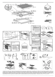
Fig. 1a
Fig. 1a
Fig. 1a
Fig. 1aFig. 1a Fig. 1b
Fig. 1b
Fig. 1b
Fig. 1bFig. 1b Fig. 1c
Fig. 1c
Fig. 1c
Fig. 1cFig. 1c
INST
INST
INST
INSTINSTALLA
ALLA
ALLA
ALLAALLATION
TION
TION
TIONTION
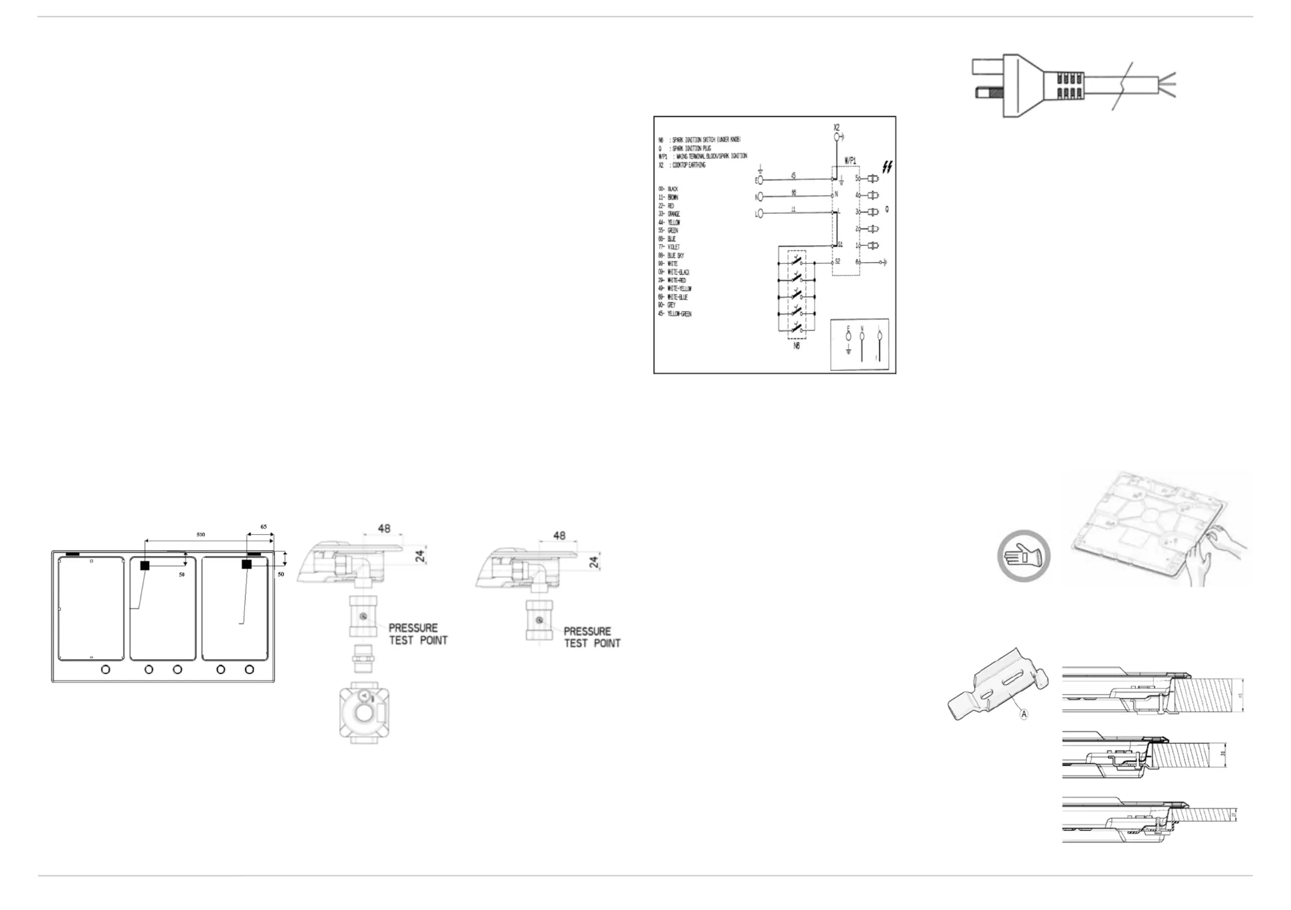
GAS CONNECTION
GAS CONNECTION
GAS CONNECTION
GAS CONNECTIONGAS CONNECTION
1.
1.
1.
1.1. Check the “gas type” sticker attached to the hotplate. Details of the injector sizes used are recorded on the data plate
located on the base of the appliance.
2.
2.
2.
2.2. This appliance shall be installed in accordance with installation requirements of the local gas authority of the appropriate
installation code. The gas supply system must comply with local regulations to the current relevant gas standard (AS/
NZS 5601 current edition).
3.
3.
3.
3.3. Before installing the hotplate consider the location of the gas supply and routing the gas line. (Refer Fig. 1).
4.
4.
4.
4.4. For ULPG models the gas supply for the hotplate must be regulated to a pressure of 2.75kPa. The gas inlet connection
fitting is ½” B.S.P male thread (in compliance with ISO 7 thread).
5.
5.
5.
5.5. For NG models the gas supply is connected to a regulator which is supplied. The inlet connection has ½” B.S.P male
thread. IT IS ESSENTIAL THAT THE ELBOW ON THE APPLIANCE BE HELD FIRMLY WITH A SPANNER. DO NOT
OVER TIGHTEN. The regulated pressure for NG is 1.00kPa.
6.
6.
6.
6.6. A manual shut-off valve must be installed in the gas line, in an accessible position external to the hotplate, so that in the
event of an emergency or service, the gas supply can be shutoff.
7.
7.
7.
7.7. For gas inlet position of appliance refer Fig. 2 for NG and fig.3 for ULPG. After installing the gas supply and making all
connections check thoroughly for possible leaks. Turn all control knobs on the unit to “OFF” position. Open the valve
on the gas supply. Using a soap and water solution check each gas connection one at a time, by brushing the solution
over connection. Presence of bubbles will indicate a leak. Tighten the fitting and re-check for leaks. If it is not possible to
correct the leak, replace fitting. Under no circumstance use matches or flame for checking leaks.
8.
8.
8.
8.8. Turn on appliance gas cock and light each burner. Check for a clear blue flame without yellow tipping. If burners shows
any abnormalties check the following:
- Burner cap on correctly
- Burner positioned correctly
- Burner vertically aligned with injector nipple
9.
9.
9.
9.9. In some cases the burners will fail to ignite immediately and will seem to 'blow's lightly when they do ignite, this is usually
due to air in the gas pipe which should clear itself within seconds of operation.
10.
10.
10.
10.10. If after following the instructions given, satisfactory performance cannot be obtained, contact the local gas authority for
advice and assistance.
W
W
W
WWARNING: Appliance not suitabl
ARNING: Appliance not suitabl
ARNING: Appliance not suitabl
ARNING: Appliance not suitablARNING: Appliance not suitable for co
e for co
e for co
e for coe for connection with f
nnection with f
nnection with f
nnection with fnnection with flexible hose assembly
lexible hose assembly
lexible hose assembly
lexible hose assemblylexible hose assembly.
.
.
..
ELECTRICAL
ELECTRICAL
ELECTRICAL
ELECTRICAL ELECTRICAL
CONNECTION
CONNECTION
CONNECTION
CONNECTION CONNECTION
POINT
POINT
POINT
POINTPOINT
GAS CONNE
GAS CONNE
GAS CONNE
GAS CONNEGAS CONNECTION
CTION
CTION
CTION CTION
POINT
POINT
POINT
POINTPOINT
Fig. 1
Fig. 1
Fig. 1
Fig. 1Fig. 1
Fig. 2
Fig. 2
Fig. 2
Fig. 2Fig. 2
Fig. 3
Fig. 3
Fig. 3
Fig. 3Fig. 3
ELECTRICAL CONNECTION
ELECTRICAL CONNECTION
ELECTRICAL CONNECTION
ELECTRICAL CONNECTIONELECTRICAL CONNECTION
•
•
•
•• The electrical connections
The electrical connections
The electrical connections
The electrical connectionsThe electrical connections must comply with local
must comply with local
must comply with local
must comply with local must comply with local
regulations.
regulations.
regulations.
regulations.regulations.
• The data relevant to the voltage and power
absorption are indicated on the rating plate.
•
•
•
•• The earthing of this appliance is compulsory by law
The earthing of this appliance is compulsory by law
The earthing of this appliance is compulsory by law
The earthing of this appliance is compulsory by lawThe earthing of this appliance is compulsory by law.
.
.
..
•
•
•
•• The manufacturer
The manufacturer
The manufacturer
The manufacturer The manufacturer cannot be he
cannot be he
cannot be he
cannot be hecannot be held responsi
ld responsi
ld responsi
ld responsild responsible for any injury
ble for any injury
ble for any injury
ble for any injury ble for any injury to persons or animals or dama
to persons or animals or dama
to persons or animals or dama
to persons or animals or damato persons or animals or damage to property arising from
ge to property arising from
ge to property arising from
ge to property arising from ge to property arising from
failure to comply with these requirement
failure to comply with these requirement
failure to comply with these requirement
failure to comply with these requirementfailure to comply with these requirements.
s.
s.
s.s.
•
•
•
•• When the hob is installed, provide a single-pole circui
When the hob is installed, provide a single-pole circui
When the hob is installed, provide a single-pole circui
When the hob is installed, provide a single-pole circuiWhen the hob is installed, provide a single-pole circuit breaker with a contact se
t breaker with a contact se
t breaker with a contact se
t breaker with a contact set breaker with a contact separation
paration
paration
paration paration of at least 3 mm
of at least 3 mm
of at least 3 mm
of at least 3 mmof at least 3 mm.
.
.
..
•
•
•
•• If necessary
If necessary
If necessary
If necessaryIf necessary, the electrical power cable must be
, the electrical power cable must be
, the electrical power cable must be
, the electrical power cable must be, the electrical power cable must be replaced ex
replaced ex
replaced ex
replaced ex replaced exclusively with a power cab
clusively with a power cab
clusively with a power cab
clusively with a power cabclusively with a power cable ha
le ha
le ha
le hale having identical characteristics
ving identical characteristics
ving identical characteristics
ving identical characteristics ving identical characteristics
to the original supplied by the manufac
to the original supplied by the manufac
to the original supplied by the manufac
to the original supplied by the manufacto the original supplied by the manufacturer (type H05V2V2-F T90°C or H05RR
turer (type H05V2V2-F T90°C or H05RR
turer (type H05V2V2-F T90°C or H05RR
turer (type H05V2V2-F T90°C or H05RRturer (type H05V2V2-F T90°C or H05RR-F).
-F).
-F).
-F). -F).
This operation must be performed by a Qu
This operation must be performed by a Qu
This operation must be performed by a Qu
This operation must be performed by a QuThis operation must be performed by a Qualified T
alified T
alified T
alified Talified T
echnician or Authorised P
echnician or Authorised P
echnician or Authorised P
echnician or Authorised Pechnician or Authorised Person.
erson.
erson.
erson.erson.
AS
AS
AS
ASASS
S
S
SSEM
EM
EM
EMEMB
B
B
BBL
L
L
LLY
Y
Y
YY
After having cleaned the perimet
After having cleaned the perimet
After having cleaned the perimet
After having cleaned the perimetAfter having cleaned the perimeter surface,
er surface,
er surface,
er surface,er surface, apply the supplied gasket to t
apply the supplied gasket to t
apply the supplied gasket to t
apply the supplied gasket to t apply the supplied gasket to the hob as
he hob as
he hob as
he hob as he hob as
shown in the figure.
shown in the figure.
shown in the figure.
shown in the figure.shown in the figure.
Position the hob in the worktop opening made respecting the dimensions indicated in the Product Description Sheet.
Note: the power supply cabl
Note: the power supply cabl
Note: the power supply cabl
Note: the power supply cablNote: the power supply cable mu
e mu
e mu
e mue must be long enough to permit its upward extraction.
st be long enough to permit its upward extraction.
st be long enough to permit its upward extraction.
st be long enough to permit its upward extraction.st be long enough to permit its upward extraction.
To secure the hob, use the brackets (A
A
A
AA) provided with it.
Fit the brackets into the relevant bores shown by the
arrow and fasten them by means of their screws in
accordance with the thickness of the worktop (see figures
on the right).
Earth
Earth
Earth
EarthEarth
(yellow/green)
(yellow/green)
(yellow/green)
(yellow/green)(yellow/green)
L
L
L
LL
N
N
N
NN
230 - 240 V
To
To
To
ToTop
p
p
pp 4
4
4
4 40
0
0
00 m
m
m
m mm
m
m
mm
T
T
T
TT
op 30 mm
op 30 mm
op 30 mm
op 30 mmop 30 mm
To
To
To
ToTop
p
p
pp 2
2
2
2 20
0
0
00 m
m
m
m mm
m
m
mm
Produktspezifikationen
| Marke: | Whirlpool |
| Kategorie: | Herd |
| Modell: | GMF 7522/IXL |
| Breite: | 730 mm |
| Tiefe: | 510 mm |
| Gewicht: | 10300 g |
| Produktfarbe: | Edelstahl |
| Steuerung: | Drehregler |
| Höhe: | 47 mm |
| AC Eingangsspannung: | 230 V |
| AC Eingangsfrequenz: | 50 Hz |
| Eingebautes Display: | Nein |
| Verpackungsbreite: | 770 mm |
| Verpackungstiefe: | 595 mm |
| Verpackungshöhe: | 155 mm |
| Paketgewicht: | 11000 g |
| Geräteplatzierung: | Integriert |
| Kochfeldtyp: | Gaskochfeld |
| Anzahl Herdplatten/Kochzonen: | 5 Zone(n) |
| Anzahl der Gasbrenner: | 5 Zone(n) |
| Anzahl der elektrischen Herdplatten: | 0 Zone(n) |
| Typ Kochzone 1: | Groß |
| Kochzone 1 Form: | Rund |
| Position Kochzone 1: | Hinten links |
| Stromquelle Kochzone 1: | Gas |
| Leistung Kochzone 1: | 3000 W |
| Typ Kochzone 2: | Regelmäßig |
| Kochzone 2 Form: | Rund |
| Position Kochzone 2: | Links vorne |
| Brenner/Kochzone 2 Stromquelle: | Gas |
| Leistung Kochzone 2: | 1650 W |
| Typ Kochzone 3: | Extragroß |
| Kochzone 3 Form: | Rund |
| Position Kochzone 3: | Mittig |
| Stromquelle Kochzone 2: | Gas |
| Leistung Kochzone 3: | 3700 W |
| Typ Kochzone 4: | Regelmäßig |
| Kochzone 4 Form: | Rund |
| Position Kochzone 4: | Hinten rechts |
| Stromquelle Kochzone 3: | Gas |
| Leistung Kochzone 4: | 1650 W |
| Steuerungsposition: | Vorne oben |
| Anschlusswert (Gas): | 12300 W |
| Art der Oberfläche: | Edelstahl |
| Durchmesser Standardherdplatten/-kochzonen: | 75 mm |
| Stromquelle Kochzone 4: | Gas |
| Typ Kochzone 5: | Köcheln |
| Leistung Kochzone 5: | 1000 W |
| Durchmesser großer Herdplatten/Kochzonen: | 100 mm |
| Standard Herdplatte/Kochzone: | 1650 W |
| Große Herdplatte/Kochzone: | 3000 W |
| Zündsicherung: | Ja |
| Elektrische Zündung: | Ja |
| Pfannenunterlagenmaterial: | Eisenguss |
| Schmorplatte/ Kochzone: | 1000 W |
| Extra große Hochgeschwindigkeitsherdplatte: | 5000 W |
| Garkochzonendurchmesser: | 50 mm |
| Durchmesser extragroße Schnellkochzone: | 130 mm |
| Kochzone 5 Form: | Rund |
| Position Kochzone 5: | Vorne rechts |
| Wok-Brennerleistung: | 3700 W |
| Wokbrenner: | Ja |
| Wokbrennerposition: | Mittel |
Brauchst du Hilfe?
Wenn Sie Hilfe mit Whirlpool GMF 7522/IXL benötigen, stellen Sie unten eine Frage und andere Benutzer werden Ihnen antworten
Bedienungsanleitung Herd Whirlpool

30 Juli 2025

30 Juli 2025
30 Juli 2025
30 Juli 2025
30 Juli 2025
30 Juli 2025
30 Juli 2025

30 Juli 2025
30 Juli 2025
30 Juli 2025
Bedienungsanleitung Herd
- Wilfa
- Sogo
- Avantco
- Mestic
- Stiebel Eltron
- Gourmia
- Olsberg
- Ernesto
- SilverCrest
- Kago
- Dovre
- Falcon
- ZLine
- Well Straler
- Oranier
Neueste Bedienungsanleitung für -Kategorien-

30 Juli 2025
30 Juli 2025

30 Juli 2025
30 Juli 2025
30 Juli 2025

30 Juli 2025

30 Juli 2025

30 Juli 2025

29 Juli 2025