Braeburn 229050 Bedienungsanleitung
Braeburn Nicht kategorisiert 229050
Lies die bedienungsanleitung für Braeburn 229050 (2 Seiten) kostenlos online; sie gehört zur Kategorie Nicht kategorisiert. Dieses Handbuch wurde von 10 Personen als hilfreich bewertet und erhielt im Schnitt 4.2 Sterne aus 4 Bewertungen. Hast du eine Frage zu Braeburn 229050 oder möchtest du andere Nutzer dieses Produkts befragen? Stelle eine Frage
Seite 1/2
Designed to Interface with Most Heating and Cooling Systems
These relays sense current rather than measure voltage, making them more reliable. They are less expensive than using traditional flow
switches, pressure switches or other types of relays. The relay installs around the blower motor’s common lead and interface easily
into the circuitry.
The current sensing relay case is constructed from high-impact plastic. The lead wire bracket is protected by a soft sponge insert, in
order to prevent damage to the motor/blower wire and/or accidental contact with any metal.
Installation Instructions
Common
Blower Lead
5 Amp. Min.
24 or 120 VAC.
L
O
A
D
229050 and 229051 Current Sensing Relays
General Installation Procedures
Important:
The wire lead bracket needs to carry a minimum of 5.0 amps for proper operation. If the current draw is less than 5.0 amps,
wrap the lead wire around the bracket so that it passes between the bracket and relay housing two or more times.
Caution:
Turn off all power to the furnace motor circuit and cabinet.
1. Follow the step-by-step instructions for
mounting the humidifier, found in the
humidifier installation manual.
2. Please follow these wiring instructions:
A.Turn off electrical power to the
furnace. Attach the current sensing
relay around the common lead of
the furnace blower motor. The relay
must be located at least 3” from any
transformer. Make sure the relay’s
metal bracket does not touch any
other metal. (See detail A)
B. Confirm the voltage of the switched
load matches the current sensing relay.
C. Wire the current sensing relay as
required for this installation. Refer to
the figures shown below as reference.
For Digital Humidistats, refer to the
Digital Humidistat wiring diagrams.
3. Follow the instructions supplied with the
humidifier to complete the installation.
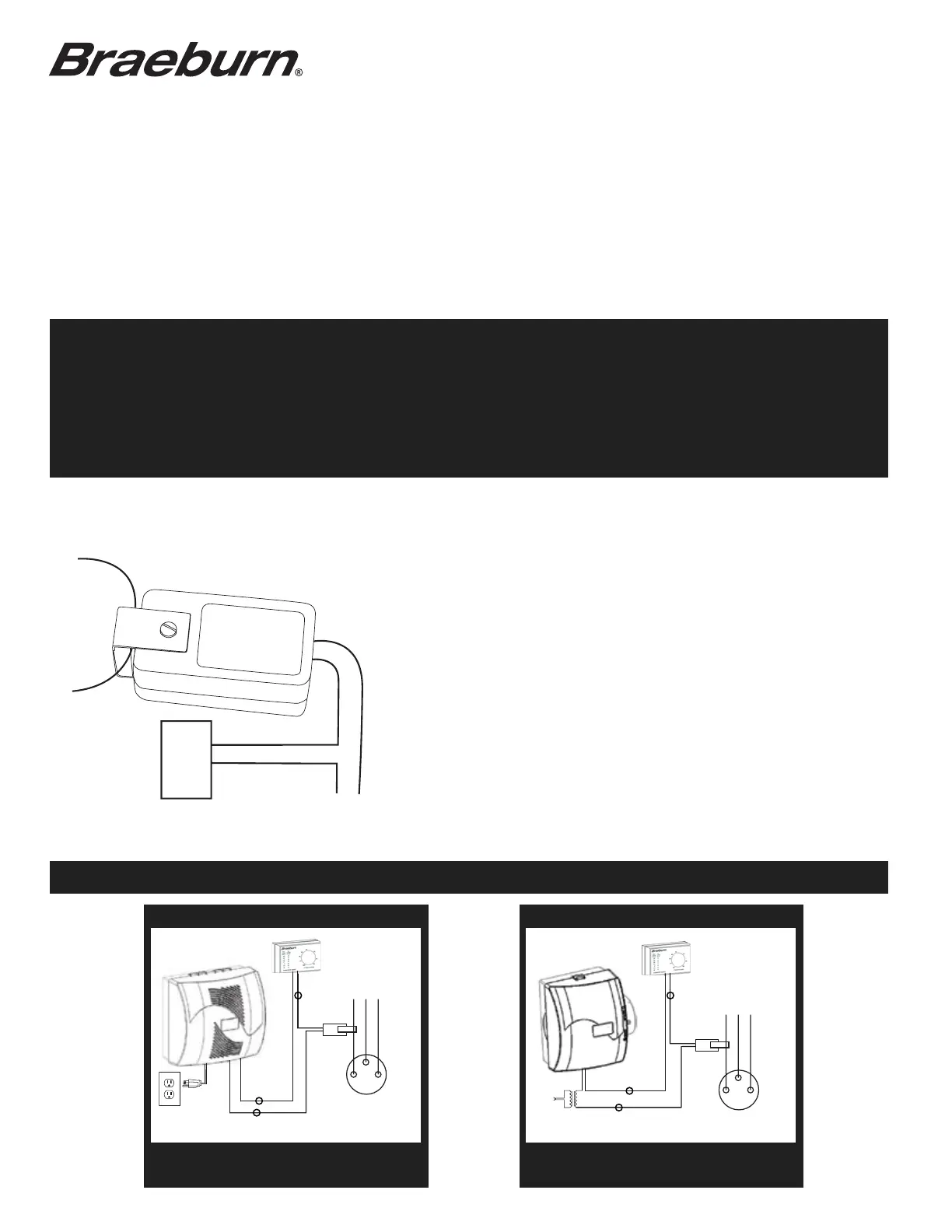
Model 229050 Wiring Diagrams (24 Volt)
120V
120 V24V
Bypass Humidifier
BRAEBURN MODELS 220700/220750BRAEBURN MODELS 220500/220550 & 220600/220650
Detail A
Z
X
YELLOW LEA
D
YELLOW
LEAD
Y
COMMON
LEAD
FURNACE
BLOWER
MOTOR
FURNACE
BLOWER
MOTOR
CURRENT
SENSING
RELAY
229100229100
COMMON
LEAD
CURRENT
SENSING
RELAY
X
Z
Y
229050 (24-volt) and 229051 (120-volt) Current Sensing Relays
229050
Fan Powered Humidifier
229050
Produktspezifikationen
| Marke: | Braeburn |
| Kategorie: | Nicht kategorisiert |
| Modell: | 229050 |
Brauchst du Hilfe?
Wenn Sie Hilfe mit Braeburn 229050 benötigen, stellen Sie unten eine Frage und andere Benutzer werden Ihnen antworten
Bedienungsanleitung Nicht kategorisiert Braeburn

17 Februar 2026
17 Januar 2026
17 Januar 2026
16 Januar 2026
14 Januar 2026
13 Januar 2026
13 Januar 2026
13 Januar 2026
12 Januar 2026
12 Januar 2026
Bedienungsanleitung Nicht kategorisiert
Neueste Bedienungsanleitung für -Kategorien-
2 April 2026
2 April 2026
2 April 2026
2 April 2026
2 April 2026
2 April 2026
2 April 2026
2 April 2026
2 April 2026
2 April 2026