Crestron MPC-M20-B-T Bedienungsanleitung
Crestron Kabelloser Presenter MPC-M20-B-T
Lies die bedienungsanleitung für Crestron MPC-M20-B-T (2 Seiten) kostenlos online; sie gehört zur Kategorie Kabelloser Presenter. Dieses Handbuch wurde von 50 Personen als hilfreich bewertet und erhielt im Schnitt 4.4 Sterne aus 9 Bewertungen. Hast du eine Frage zu Crestron MPC-M20-B-T oder möchtest du andere Nutzer dieses Produkts befragen? Stelle eine Frage
Seite 1/2
DOGUIDE
DO Install the Device
The MPC-M10, MPC-M20, and MPC-M25 media presentation controllers
are designed to install into a standard 3-gang electrical box. After the
facility control network has been installed and veried, use the following
procedure to install the device.
NOTE: The MPC-M10, MPC-M20, and MPC-M25 are functionally similar,
and they share the same installation and programming process. For
simplicity within this guide, the term "MPC device" is used except where
noted.
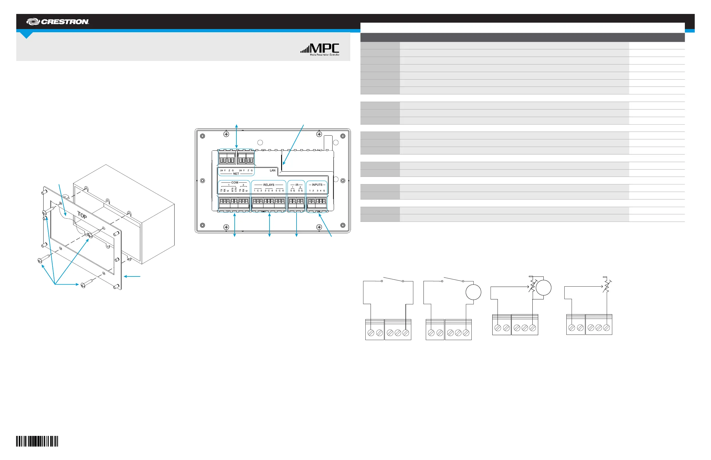
Attach the Mounting Plate into an Electrical Box
1. Turn the system power off.
2. Use the four included 6-32 x 3/4" screws to attach the mounting plate
to the electrical box.
3. Attach the mounting plate ground wire to an earth ground.
NOTE: Ensure the unit is properly grounded.
Connect the Device
Route all appropriate cables through the electrical box, and then attach
them to the rear of the MPC device.
NOTE: All cable connections must be made prior to attaching the MPC
device to the mounting plate.
When making connections to the MPC device, note the following:
•Use Crestron
®
power supplies for Crestron equipment.
•Apply power after all connections to the device have been made.
•The included power cable cannot be extended.
NOTE: COM 2, IR 2, and RELAYS 3, 4, 5, and 6 are found only on the
MPC-M25.
NOTE: When connecting the included power supply to the NET connector
on the unit, make sure the lead with the white stripes connects to the
terminal marked “24.” The other lead connects to the terminal marked “G.”
Depending on the application, the MPC device INPUTS can be wired multiple ways. Refer to the following diagrams when wiring INPUTS.
WARNING: Incorrect wiring may damage the MPC device.
NOTE: The settings for the pull-up resistor are specied in the SIMPL Windows program. For more information, refer to the SIMPL Windows help le.
MPC-M10/MPC-M20/MPC-M25
MPC Media Presentation Controller
DO Check the Box
QUANTITYPRODUCTCOLORPART NUMBER
2Connector, Butt SpliceRed2021836
1Plate, Mounting4506280
1Power Cord, 6' 7" (2 m)2001134
1Power Pack, 24 Vdc 0.75 A, 100-240 Vac2045852
2Screw, 4-40 x 1/4", Pan Head, Phillips2007156
4Screw, 6-32 x 3/4", Truss Head, Combo2009211
1Tool, 1/16" Allen Wrench, L-shape, 3" Blade2022867
For MPC-M10-W, MPC-M20-W, MPC-M25-W only
1Labels, Sources, 100 Piece SetWhite4509400
1Labels, Actions, 100 Piece SetWhite4509402
4Screw, 4-40 x 1/2", Button Head, Hex2021396
For MPC-M10-B-T, MPC-M20-B-T, MPC-M25-B-T only
1Labels, Sources, 100 Piece SetBlack4509401
1Labels, Actions, 100 Piece SetBlack4509403
4Screw, 4-40 x 1/2", Button Head, HexBlack2021395
For MPC-M10-W and MPC-M10-B-T only
1Front Panel and Label, 10 ButtonWhite4506184
1Front Panel and Label, 10 ButtonBlack4506185
For MPC-M20-W and MPC-M20-B-T only
1Front Panel and Label, 20 ButtonWhite4506180
1Front Panel and Label, 20 ButtonBlack4506181
For MPC-25-W and MPC-25-B-T only
1Front Panel and Label, 20 ButtonWhite4506178
1Front Panel and Label, 20 ButtonBlack4506179
Input Wiring Diagrams - Digital Input Function
Input Wiring Diagrams - Analog Input Function
Ground
wire
Mounting
plate
Screws (4): 6-32 x 3/4"
NET:
To any Cresnet
®
network device
LAN:
10/100Base-T Ethernet to
LAN or web
COM:
To any RS-232
device
RELAYS:
To controllable
devices
IR:
To IRP2 or
serial devices
INPUTS:
From digital or
analog devices
+
-
Detecting a contact voltage
from a switch or relay
Analog input pull-up
resistor: disabled
Analog input pull-up
resistor: enabled
24 Vdc
max
1 2 3 4 G
1 2 3 4 G
Detecting a contact closure
from a switch or relay
Reading resistance
of a potentiometer
+
-
+
-
Reading voltage from
an analog source
Analog input pull-up
resistor: disabled
Analog input pull-up
resistor: enabled
10 Vdc
1 2 3 4 G1 2 3 4 G
Produktspezifikationen
| Marke: | Crestron |
| Kategorie: | Kabelloser Presenter |
| Modell: | MPC-M20-B-T |
| Breite: | 170.2 mm |
| Tiefe: | 56.7 mm |
| Gewicht: | 610 g |
| Höhe: | 114.3 mm |
| Lautstärkeregler: | Drehregler |
| Betriebstemperatur: | 0 - 40 °C |
| Relative Luftfeuchtigkeit in Betrieb: | 10 - 90 % |
| Vollduplex: | Ja |
| Anzahl Ethernet-LAN-Anschlüsse (RJ-45): | 1 |
| Gehäusematerial: | Kunststoff |
| Ethernet LAN Datentransferraten: | 10, 100 Mbit/s |
| LED-Anzeigen: | Activity, Link |
| RS-232 port: | 1 |
| Web-basiertes Management: | Ja |
| Speicherkapazität: | 32 MB |
| Externes Netzteil: | Ja |
| Knopfanzahl: | 15 |
| Interner Speichertyp: | SDRAM |
| Gehäusefarbe: | Schwarz |
| Reset-Knopf: | Ja |
| Wandmontage: | Ja |
| Flash-Speicher: | 8 MB |
| Statische IP: | Ja |
| Netzteil enthalten: | Ja |
| Wärmeableitung: | 17 BTU/h |
| Prozessor Architektur: | ColdFire |
| Fernbedienung (IR) output: | 1 |
| Beleuchtete Tasten: | Ja |
| USB-Port-Typ: | USB Typ-B |
| Lichtsensor: | Ja |
| Switch Protokoll: | IP, DHCP, DNS, SSL, TCP/IP, UDP/IP, CIP, SMTP, SNMP |
| Anpassbare Knöpfe: | Ja |
| Nummerntasten: | Ja |
| D-pad: | Ja |
| Fernbedienungs-Steuerübertragungsdistanz: | 15 m |
| Infrarot (IR)-Frequenzbereich: | 36 - 38 kHz |
| Ethernet/LAN: | Ja |
| Anzahl an eingebauten Relais: | 2 |
| Zurücksetzarten: | Hardware-Reset |
| NVRAM-Kapazität: | 256 KB |
| Leistungs-Klemmenleiste: | 2 |
Brauchst du Hilfe?
Wenn Sie Hilfe mit Crestron MPC-M20-B-T benötigen, stellen Sie unten eine Frage und andere Benutzer werden Ihnen antworten
Bedienungsanleitung Kabelloser Presenter Crestron

27 September 2025
21 August 2024
21 August 2024
20 August 2024
20 August 2024
26 Dezember 2023
Bedienungsanleitung Kabelloser Presenter
Neueste Bedienungsanleitung für -Kategorien-
7 Oktober 2025
6 Oktober 2025
6 Oktober 2025
29 September 2025
17 September 2025
14 September 2025
12 August 2025
4 August 2025
4 August 2025
30 Juli 2025