Eberle INSTAT 868-a1A Bedienungsanleitung
Eberle Digitale camcorder INSTAT 868-a1A
Lies die bedienungsanleitung für Eberle INSTAT 868-a1A (2 Seiten) kostenlos online; sie gehört zur Kategorie Digitale camcorder. Dieses Handbuch wurde von 54 Personen als hilfreich bewertet und erhielt im Schnitt 4.2 Sterne aus 9 Bewertungen. Hast du eine Frage zu Eberle INSTAT 868-a1A oder möchtest du andere Nutzer dieses Produkts befragen? Stelle eine Frage
Seite 1/2
5. Commissioning
BR 1 is closed
5.1 Establishing the radio link
On completion of the installation work, a link between
the INSTAT 868-r… transmitter and the radio receiver
must be established. To do this, follow this: (see g. 1)
a) Set the transmitter to “Learning mode” (see
Operating instructions for transmitter)
b. For function-1, – switching mode –
activate “Learning mode” on transmitter (A) to do
this: press the z button briey
A signal tone sounds, the signal lamp lights up
and the output is switched on briey. When the
transmitter is recognised, the signal tone ceases to
sound and the signal lamp extinguishes.
c. Terminate the “Learning mode” on the transmitter
d. Test the radio links which have just been established
(see below picture 3 and Table 1))
Commissioning the enhanced functions see
manual “Enhanced functions for 1 channel
receiver INSTAT 868-a1”
Fig. 1
One transmitter (INSTAT 868-r) controls one receiver.
INSTAT 6-a1
INSTAT 6-r1
1
A
Fig. 2
One transmitter (INSTAT 868-r) controls one receiver
A
1
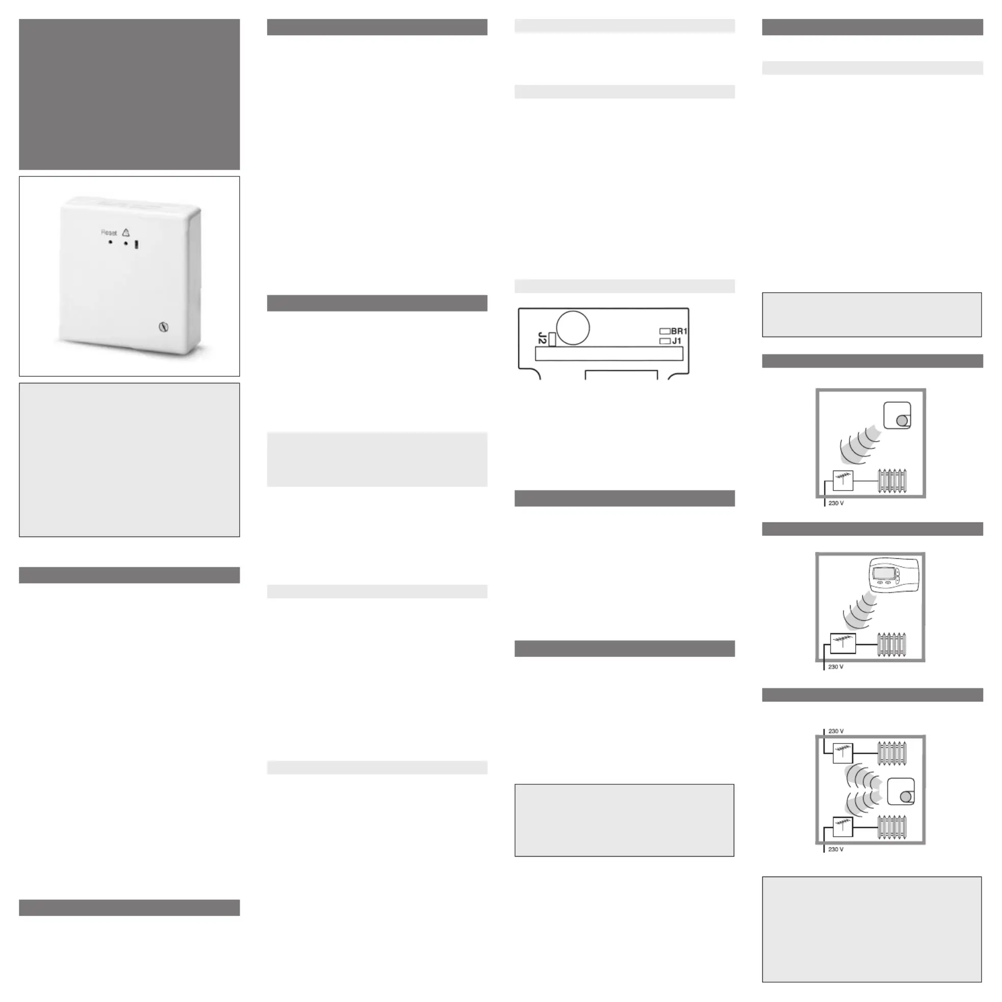
Fig. 3
One transmitter (INSTAT 868-r) controls a couple of
receivers
INSTAT 6-a1
INSTAT 6-r1
INSTAT 6-a1
1
A
A
Test of the function „switching-mode“
Receiver: press Reset
the lamp must ash one time only
Transmitter: adjust to 30°C
after ~30 sec
the output switches on
Transmitter: adjust 5°C
after ~30 sec
the output switches o
Contents:
1. Use
2. Features
3. Function description
3.1 Basic Functions
3.1.1 Function - 1, - Switching mode
3.1.2 Reversing the control action
3.1.3 Testing the radio link range
3.1.4 System demonstration
3.1.5 Signal lamp function
3.1.6 Jumper function
3.2 Enhanced functions
4. Installation
5. Commissioning
5.1 Establishing the radio link
5.2 Valve test
5.3 Quit/Reset
5.4 Power failure
5.5 Faults
5.5.1 Double addressing
5.5.2 Short time losses of the transmission
signal
5.5.3 Long time losses of the transmission
signal
5.6 Troubleshooting
6. Technical data
7. Dimensions
8. Wiring diagram
9. Examples
10. Short form instructions
1. Use
Receiver for INSTAT 868-r… (radio transmitter)
for switching:
• actuators of radiator heaters
• heating systems with switching applications
• circulating pumps (decentralised pump control)
• etc.
2. Features
• Volt-free switching of:
➩24 … 250 V AC loads
• Output functions (optional):
➩ Heating ON / OFF
➩Temperature setback ON / OFF e.g. for boilers or
other controllers
➩Pump control for up to 6 transmitters, extendable
• Reversing of control action for:
➩connecting actuators “currentless open” instead
of “currentless closed”
➩changing from summer to winter mode
(cooling instead of heating)
• Valve test function
• Radio test and system demonstration
• One transmitter can control several receiver
modules
• Self-learning address settings through
“Learning mode” in the transmitter
• button for setting of functions
• Reset button
• Signal lamp indicates initial state, faults etc.
• Monitoring of valid radio link
• Audible signal in case of faults (can be switched o)
• Emergency operation in case of loss of radio link
3. Function description
The INSTAT 868-a1 receiver converts radio signals
received from a transmitter, e.g. INSTAT 868-r … into
control signals for loads. The loads are switched by
means of a relay.
The switching state of the output is indicated by a
signal lamp.
For switching characteristics, see Installation instruc-
tions for the transmitter under item “Function descripti-
on”. For controlling the electric loads, the output can be
congured in dierent ways.
3.1 Basic Functions
3.1.1 Function - 1, - switching mode -
“One transmitter controls one switching
output”
One transmitter controls the output for heating/cooling
ON/OFF.
This function is active, if jumper BR1 is closed.
Note: For heating systems, which are in stand by mode
during summer time (e.g. electric heating), the valve
protection has to be switched o (in the transmitter).
If the valve protection is not switched o, a daily 3min.
heating will take place.
3.1.2 Reversing the control action
The switching characteristics of the output and the
signal lamp are reversed in respect of all functions
(also pump control). Due to this feature, the following
functions can be implemented.
• connecting actuators NO
• changing from summer to winter mode
(cooling instead of heating)
For cooling (summer mode) or actuators NO:
single-pole plugging of J1 jumper (One-pole plugging
prevents loss of jumper)
For heating (winter mode or actuators NC)
(= as delivered condition)
double-pole plugging J1 jumper .
3.1.3 Testing the radio link range
To determine the radio link range, follow this:
Set the transmitter to “Learning mode”:
1. Press the z button and the ”Reset” button simulta-
neously
2. Release the ”Reset” button rst, then the z button
The signal lamp lights up. The signal tone and the
output operate in the switching mode, approx.
2 sec. ON, 8 sec. OFF.
3. Now, while holding the transmitter in your hand,
walk away from the receiver until you reach the point
where the signal tone is no longer audible and the
signal lamp stops ashing. This point is the maximum
possible radio link range.
4. Always terminate this function by pressing the “Reset”
button.
5. Quit the “Learning mode” on the transmitter
As far as a free transmitter is used, existing radio links
will not be aected.
3.1.4 System demonstration
To demonstrate the radio range, see section 3.1.3
“Testing the radio link range”. If necessary, a lamp can
be connected to the output.
3.1.5 Signal lamp function
The signal lamps provide the following information:
• Output state … ON/OFF in a interval of 10 min.
or steady light may be possible
• Faults … Blinking; Duration varies
depending on type of fault
• Learning mode … ON until the link is established
or the Reset button is pressed
• Valve test … ON as long as the “Reset” is
pressed
• Testing the
radio link range … Flashing, 10 sec. interval
• Monitoring of
channels … after “Reset”
3.1.6 Jumper function
J1: open to reverse control action = cooling
J2: open to switch o the beeper
BR1: closed = only switching mode possible
open = all functions possible
One-pole plugging prevents loss of jumpers
3.2 Enhanced Functions
The functions
• pump logic control
• Time switch (Maser/Slave)
• pilote output
are described in the additional manual „Enhanced
functions for 1 channel receiver INSTAT 868-a1, no.
468931003281.
These functions are available by opening Jumper BR1.
4. Installation
Installation: e.g.
• In distribution board on DIN rail (by snap-on moun-
ting SBF 3/6)
• Directly on the wall
• If necessary, on conduit box , by means of ARA 1S
pattress.
Electrical connection
To make this connection, follow this:
Attention:
• Danger of electric shock, disconnect device from
power supply
• The device is not designed for switching „safety
extra low voltage“ (SELV)
• Loosen cover fastening screw
• Remove top part of housing
• Make the connection in compliance with the circuit
diagram (see top part of housing)
• If necessary, knock out penetration for actuator drive
cable (lower right-hand corner)
Make sure that the strain relief for the actuator drive
connection ts tight.
Caution!
The radio receiver may be installed only by a
specialist in compliance with the circuit diagram
enclosed in the top housing cover or in compliance
with these instructions. The current safety regula-
tions must be observed. Appropriate installation
measures must be taken to achieve the require-
ments of protection class II.
This radio receiver which can be installed separately,
is designed exclusively for temperature control in
dry and closed rooms and standard environments.
This electronic device was created according EN
60730, it operates according working principle 1C.
Errors possible/Subject to alterations.
Installation and
Operating Instructions
Radio receiver
.-a1A
U 468 931 003 277-5
Produktspezifikationen
| Marke: | Eberle |
| Kategorie: | Digitale camcorder |
| Modell: | INSTAT 868-a1A |
Brauchst du Hilfe?
Wenn Sie Hilfe mit Eberle INSTAT 868-a1A benötigen, stellen Sie unten eine Frage und andere Benutzer werden Ihnen antworten
Bedienungsanleitung Digitale camcorder Eberle

7 September 2025
7 September 2025
30 August 2025
30 August 2025
12 August 2025
12 August 2025
12 August 2025
2 Oktober 2024
2 Oktober 2024
26 August 2024
Bedienungsanleitung Digitale camcorder
Neueste Bedienungsanleitung für -Kategorien-
19 Januar 2026
14 Januar 2026
14 Januar 2026
13 Januar 2026
2 Januar 2026
29 Dezember 2026
27 Dezember 2025
25 Dezember 2025
23 Dezember 2025
23 Dezember 2025