EXSYS EX-1333V Bedienungsanleitung
EXSYS Nicht kategorisiert EX-1333V
Lies die bedienungsanleitung für EXSYS EX-1333V (2 Seiten) kostenlos online; sie gehört zur Kategorie Nicht kategorisiert. Dieses Handbuch wurde von 34 Personen als hilfreich bewertet und erhielt im Schnitt 4.9 Sterne aus 5 Bewertungen. Hast du eine Frage zu EXSYS EX-1333V oder möchtest du andere Nutzer dieses Produkts befragen? Stelle eine Frage
Seite 1/2
65
Kompatibilität:USB 1.1, 2.0 & 3.2
Betriebssysteme:Windows 9.x / ME / 2000 / XP / Vista / 7 / 8.x / 10 / 11 / Server 20xx /
Linux / MAC
Anschlüsse:2x 9 Pin Stecker Seriell RS232/422/485, 1x USB 2.0 BBuchse --
Lieferumfang:1333V, USB 2.0 Kabel (verschraubbar), Treiber CD, AnleitungEX-
Zertifikate:
1
BESCHREIBUNG & TECHNISCHE DATEN
Der EX1333V ist ein Modul zur Umsetzung von USB 2.0 auf zwei RS232/422/485 Schnittstel---
len mit FIFO 16C550 Port für den Anschluss von High Speed seriellen RS232/422/485 Peri--
pherie Geräten (z.B. Modem, Plotter usw.). Der EX1333V ist mit einer verschraubbaren USB -
2.0 BBuchse zum Anschluss an den PC und zwei serielle 9 Pin Stecker ausgestattet. Das USB -
Modul ist Hot Plug & Play fähig. Für die Einstellungen der I/O Adressen und Interrupts sind
keine Jumper und Einstellungen notwendig, da die Einstellungen automatisch vom System
BIOS und bei der Installation des Betriebssystems vorgenommen werden. Die verschiedenen
Übertragungsmodi können mittels den auf der Unterseite befindlichen DippSchalter eingestellt -
werden.
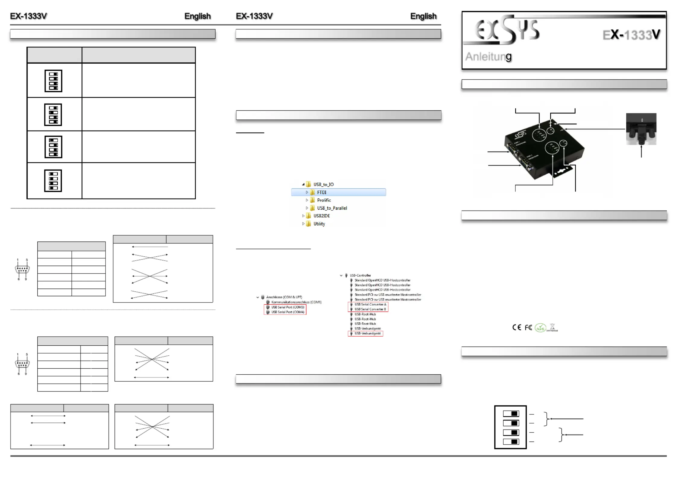
AUFBAU
Anleitun
Vers. 1.0 / 04.04.23
E1333
DIPPSCHALTER & ANSCHLÜSSE-
USB BBuchse -
(verschraubbar)
Mode LED für Port 1
Betriebs LED
TX/RX LED für Port 1
Port 1
TX/RX LED für Port 2
Port 2
Mode LED für Port 2
Es gibt zwei 4Pin DippSchalter auf der Unterseite der EX1333V. Jeder DippSchalter ist für ----
einen seriellen Port zuständig. Pin 1 und Pin 2 (markiert mit M1 und M0) haben die Funktion
zwischen den drei Modis RS232, RS422 und RS485 umzuschalten. Pin 3 und Pin 4 (markiert ---
mit TERM ON) haben die Funktion die Abschlusswiederstände für die RS422/485 Modis ein -
oder auszuschalten.
1 2 3 4
ON
M1
M0
TERM ON
TERM ON
RS- 232/422/485 Mode Schalter
Schalter für Abschlusswiederstände
HARDWAREINSTALLATION
DRIVER INSTALLATION
Because there are large differences between PCs, we can give you only a general installation ’
guide for the EX-1333V. Please refer your computers reference manual whenever in doubt.
1.-- Connect the supplied USB 2.0 cable to the USB 2.0 BPort of the EX1333V.
2.--Now connect the other end (AConnector) of the supplied USB 2.0 cable to the USB APort
on your PC.
3.When you are ready you can start your PC and continue with the point Driver Installation.„“
CLEANING
Windows
After the hardware installation Windows will recognize the device automatically and install the
drivers. If the driver shoul not be installed automatically, please insert the Driver CD into your
CD-Rom drive (e.g. Drive D:) and open the folder USB_to_IO/FTDIPlease select the folder „“.
with your operating system and install the driver (see Picture). Follow the hardware assistant
and finish the installation. Restart your PC in any case after installing the drivers.Important!
For cleaning please use only a dry fluff less cloth and remove the dirt with gently pressure. In
the area of the connectors please make sure that no fibres from the cloth remain in the connect-
ors. Attention! Never use a moist or wet cloth for cleaning!
CHECK INSTALLED DRIVER
Open the ><. Now you should see at Device manager„Ports (COM & LPT)USB“ and „-
Controller “the following new entries:
If you see these or a similar information’s the device is installed correctly.
DIPPSWITCH & CONNECTORS -
DippSwitchDescription-
RS-- 485 2wire Mode
(Factory Setting)
RS-- 485 4wire Mode
RS- 422 Mode
- RS232 Mode
(Pin 1 and Pin 2 must be set to Note:
OFF to operate in the
RS- 232 mode)
1
ON
9 Pin Serial Connector
PinSignalPinSignal
16DSRDCD
2RXD7RTS
3TXD8CTS
4DTR9 RI
5GND
DB 9M
RS-232 Cable Wiring
DB9 (EX1333V)232 (Device)- RS-
11DCD DCD
2RXD2RXD
3TXD3TXD
4DTR4DTR
5GND5GND
6DSR6DSR
7RTS7RTS
8CTS8CTS
RS- 232 Pin Assignments:
DB 9M
RS- 422/485 Pin Assignments:
DB9 (EX1333V)422 (Device)- RS-
1TXD1TXD- -
2TXD+2TXD+
3RXD+3RXD+
4RXD4RXD- -
5GND5GND
9 Pin Serial Connector
PinSignalPinSignal
1TXD (DATA)6-- NC
2TXD+ (DATA+)7 NC
3RXD+8 NC
4RXD9- NC
5GND
RS-422 Cable Wiring
2341
ON
2341
ON
2341
ON
234
DB9 (EX1333V)485 (Device)- RS-
1TXD1TXD- -
2TXD+2TXD+
3RXD+3RXD+
4RXD4RXD- -
5GND5GND
RS--485 2wire Cable Wiring485 4wire Cable WiringRS--
DB9 (EX1333V)485 (Device)- RS-
1TXD1TXD- -
2TXD+2TXD+
3RXD+3RXD+
4RXD4RXD- -
5GND5GND
Produktspezifikationen
| Marke: | EXSYS |
| Kategorie: | Nicht kategorisiert |
| Modell: | EX-1333V |
| Breite: | 106 mm |
| Tiefe: | 113 mm |
| Gewicht: | 500 g |
| Produktfarbe: | Schwarz |
| Übertragungstechnik: | Kabelgebunden |
| Höhe: | 24 mm |
| Stecker: | 9p RS-232/422/485 (x2) |
| Anzahl USB 2.0 Anschlüsse: | 1 |
| Betriebstemperatur: | 0 - 55 °C |
| Relative Luftfeuchtigkeit in Betrieb: | 5 - 95 % |
| Temperaturbereich bei Lagerung: | -40 - 75 °C |
| Mac-Kompatibilität: | Nein |
| Kompatible Betriebssysteme: | Windows 98SE/ME/XP/Vista/7\nLinux |
| Unterstützte Protokolle: | TX, RX |
| Hostschnittstelle: | USB |
| Datenübertragungsrate: | 480 Mbit/s |
| Anzahl Anschlüsse: | 3 |
| Chipsatz: | FTDI |
Brauchst du Hilfe?
Wenn Sie Hilfe mit EXSYS EX-1333V benötigen, stellen Sie unten eine Frage und andere Benutzer werden Ihnen antworten
Bedienungsanleitung Nicht kategorisiert EXSYS

14 März 2026
26 September 2025
26 September 2025
6 September 2025
6 September 2025
5 September 2025
31 Juli 2025
25 Juli 2025
24 Juli 2025
24 Juli 2025
Bedienungsanleitung Nicht kategorisiert
Neueste Bedienungsanleitung für -Kategorien-
3 April 2026
3 April 2026
3 April 2026
3 April 2026
3 April 2026
3 April 2026
3 April 2026
3 April 2026
3 April 2026
3 April 2026