EXSYS EX-43360 Bedienungsanleitung
EXSYS Nicht kategorisiert EX-43360
Lies die bedienungsanleitung für EXSYS EX-43360 (2 Seiten) kostenlos online; sie gehört zur Kategorie Nicht kategorisiert. Dieses Handbuch wurde von 11 Personen als hilfreich bewertet und erhielt im Schnitt 4.0 Sterne aus 5 Bewertungen. Hast du eine Frage zu EXSYS EX-43360 oder möchtest du andere Nutzer dieses Produkts befragen? Stelle eine Frage
Seite 1/2
651
JUMPEREINSTELLUNG & ANSCHLÜSSE
BESCHREIBUNG & TECHNISCHE DATEN
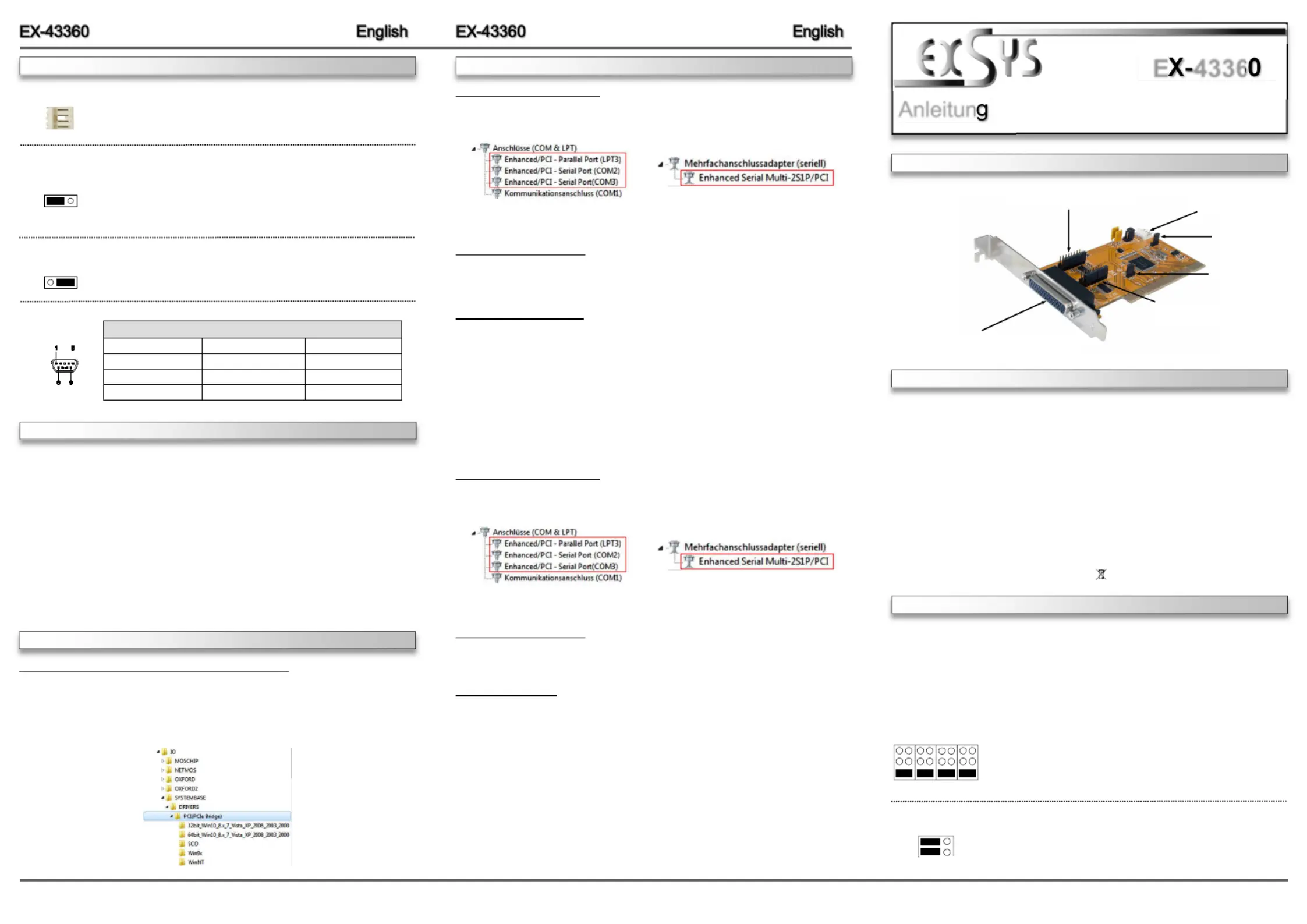
AUFBAU
Anleitun
Vers. 1.0 / 22.05.17
E4336
JUMPERSETTING & CONNECTORS
CHECK INSTALLED DRIVER
Open the >Device manager<. Now you should see at „“ and at Ports (COM & LPT)
„“ the following new entry's:Multifunction Adapter
If you see this or a similar information the device is installed correctly.
CHANGE PORT NUMBER
If you like to change the port number for example COM3 to COM5, open the „Device Manager”
click at „COM3 Settings ”,„”and then „Advance”. There you can change between COM3 till
COM256.
Windows Server 20xx
After completing the hardware installation, the operating system will automatically the card and
install this! If the driver should not be installed automatically, insert the driver CD into you CD-
ROM drive (eg drive D:) and then open the folder „IO/SYSTEMBASE/DRIVERS/PCI(PCIe
Bridge)“. Please select the folder with your operating system and install the driver (see Picture).
Follow the hardware assistant and finish the installation. Restart your PC in any Important!
case after installing the drivers.
Use the following driver for the following Windows Server Version.
Windows Server 2003=XP Driver
Windows Server 2008=VISTA Driver
Windows Server 2008R2=Windows 7 Driver
Windows Server 2012=Windows 8.x Driver
Windows Server 2012R2=Windows 10 Driver
CHECK INSTALLED DRIVER
Open the >Device manager<. Now you should see at „“ and at Ports (COM & LPT)
„“ the following new entry's:Multifunction Adapter
If you see this or a similar information the device is installed correctly.
CHANGE PORT NUMBER
If you like to change the port number for example COM3 to COM5, open the „Device Manager”
click at „COM3 Settings ”,„”and then „Advance”. There you can change between COM3 till
COM256.
Linux / SCO Unix
The drivers are located in the following folder on our driver CD:
"IO/SYSTEMBASE/DRIVERS/PCI(PCIe Bridge)/SCO"
Because each individual distribution and kernel version of Linux is different, sadly we cant
provide a installation instruction. Please refer to the installation manual for standard IO ports
from your Unix/Linux version! In some newer versions of Linux the card will even be installed
automatically after starting Linux.
DRIVER INSTALLATION
JP7:Power auf Pin 1,4,8,9
des 9 Pin Stecker Ein/Aus
JP6:Power auf Pin 1,4,8,9
des 9 Pin Stecker Ein/Aus
Die EX43360 ist eine 32Bit PCI Karte mit 2 seriellen FIFO 16C550 Ports, für den Anschluss --
von HighSpeed seriellen RS232 Peripherie Geräten (z.B. Terminal, Modem, Plotter usw.) und --
einem Parallelen Bi-Direktionalen EPP/ECP Ausgang für den Anschluss von Peripheriegeräten mit
Standard Centronics Interface (z.B. Drucker, Scanner, Laufwerke usw.). Die EX43360 nutzt den -
16C550 UART Chipsatz, der die neueste High-SpeedInterfaceTechnologie beinhaltet. Die --
Karte gewährleistet so eine sichere Datenübertragung und exzellente Performance von bis zu
115KBaud/s für jedes angeschlossene serielle Gerät! Sie unterstützt den 32-und 64Bit PCI -
bzw. PCIX Bus mit 5 Volt und 3,3 Volt. Es ist nicht möglich die I/O Adressen und Interrupts -
manuell einzustellen, da die Einstellungen der Karte vom System (BIOS) und beim installieren
des Betriebssystems automatisch vorgenommen werden. Es besteht bei Bedarf die Möglichkeit,
+5V oder +12V auf einen von vier möglichen Pins der beiden 9 Pin Stecker zu legen (POS
Kompatibilität:PCI oder PCIX, 33Mhz-
Betriebssysteme:Windows NT 4.0/ 9x/ 2000/ XP/ Vista/ 7/ 8.x/ 10/ Server 20xx/ Linux
Anschlüsse:2x 9 Pin Seriell DSub Stecker, 1x 25 Pin Parallel Buchse-
Lieferumfang:EX43360, Treiber CD, Anleitung, Low Profile Bügel, Oktopus Kabel-
Zertifikate:
CE
CE
CE
CECE
/ FCC / RoHS / WEEE DE97424562 / WHQL
Mit der EX43360 haben Sie die Möglichkeit +5V oder +12V auf einen der folgenden vier Pins -
der Stecker und zu konfigurieren:S1 S2
Achtung! Nur konfigurieren wenn für das Peripheriegerät wirklich +5Volt oder +12Volt benötigt
wird. Für normale Anwendung den Jumper nicht verändern, sonst werden Ihre Geräte beschä-
digt!
JP6 & JP7:
(S1 & S2)
+5V
+12V
DIS
Pin 9Pin 8Pin 4Pin 1
Achtung!Es darf pro Pin immer nur eine Spannung eingestellt
werden!
+5V: +5V auf den jeweiligen Pin des Anschlusses
+12V: +12V auf den jeweiligen Pin des Anschlusses
DIS: (Werkseinstellung)Keine Spannung auf dem Anschluss
JP8:
JP8 gesetzt auf = +5 oder +12V kommt vom PCIBus PCI-(Werkseinstellung)
JP8 gesetzt auf = +5 oder +12V kommt vom PC Netzteil AUX
PCI AUX
+5V
+12V
J7: Anschluss für Strom
vom PC Netzteil
JP5:LPT Ein/Aus
JP3:PME Ein/Aus
S1S2 & P1:- 44 Pin Stecker zu 2 x 9 Pin
Serieller & 1x Parallel Anschluss
If you are ready with the jumper settings, please proceed with the following installation instructions.
Because there are large differences between PC’s, we can give you only a general installation
guide. Please refer to your computer’s reference manual whenever in doubt.
1.Turn off the power to your computer and any other connected peripherals.
2.Remove the mounting screws located at the rear and/ or sides panels of your Computer and
gently slide the cover off.
3.Locate an available expansion slot and remove its covers from the rear panel of your comput-
er. Make sure it is the right expansion slot for the card (see card description)
4.Align the card with the expansion slot, and then gently but firmly, insert the card. Make sure
the card is seated and oriented correctly. Never insert the card by force!
5.Then connect the card with a screw to the rear panel of the computer case.
6.Gently replace your computer’s cover and the mounting screws.
DB 9M:
PinSignalPinSignalPinSignal
1CDC4DTR7RTS
2RXD5GROUND8CTS
3TXD6DSR9RI
Serial 9 Pin DSUB Connector-
Windows NT 4.0/ 9x/ 2000/ XP/ Vista/ 7/ 8.x/ 10
After completing the hardware installation, the operating system will automatically the card and
install this! If the driver should not be installed automatically, insert the driver CD into you CD-
ROM drive (eg drive D:) and then open the folder „IO/SYSTEMBASE/DRIVERS/PCI(PCIe
Bridge)“. Please select the folder with your operating system and install the driver (see Picture).
Follow the hardware assistant and finish the installation. Restart your PC in any Important!
case after installing the drivers.
HARDWAREINSTALLATION
DRIVER INSTALLATION
DIS(Factory Setting) =The function PME is disable.
ENA= The function PME is enable. Now the card can be activate
the computer through the serial ports.
But this should not be adjusted for standard applications.
JP3:
J7:
1 +5V
2 GND
3 GND
4 +12V
For aux power (JP8), J7 must be connected to pc power supply! If not
the card won’t work.
DIS = LPT Port ist inactive.
ENA(Factory Setting)= LPT Port ist activ.
JP5:
DIS | ENA
DIS | ENA
Produktspezifikationen
| Marke: | EXSYS |
| Kategorie: | Nicht kategorisiert |
| Modell: | EX-43360 |
Brauchst du Hilfe?
Wenn Sie Hilfe mit EXSYS EX-43360 benötigen, stellen Sie unten eine Frage und andere Benutzer werden Ihnen antworten
Bedienungsanleitung Nicht kategorisiert EXSYS

14 März 2026
26 September 2025
26 September 2025
6 September 2025
6 September 2025
5 September 2025
31 Juli 2025
25 Juli 2025
24 Juli 2025
24 Juli 2025
Bedienungsanleitung Nicht kategorisiert
Neueste Bedienungsanleitung für -Kategorien-
3 April 2026
3 April 2026
3 April 2026
3 April 2026
3 April 2026
3 April 2026
3 April 2026
3 April 2026
3 April 2026
3 April 2026