EXSYS EX-44062 Bedienungsanleitung
EXSYS Nicht kategorisiert EX-44062
Lies die bedienungsanleitung für EXSYS EX-44062 (2 Seiten) kostenlos online; sie gehört zur Kategorie Nicht kategorisiert. Dieses Handbuch wurde von 10 Personen als hilfreich bewertet und erhielt im Schnitt 4.5 Sterne aus 9 Bewertungen. Hast du eine Frage zu EXSYS EX-44062 oder möchtest du andere Nutzer dieses Produkts befragen? Stelle eine Frage
Seite 1/2
651
Die EX44062 ist eine PCIExpress serielle RS232 Karte mit 2 seriellen FIFO 16C550 Ports, ---
für den Anschluss von HighSpeed seriellen RS232 Peripherie Geräten (z.B. Terminal, Mo---
dem, Plotter usw.). Der serielle PCIExpress Bus unterstützt dabei optimal die Leistung des -
schnellen Systembase Chipset. Die Karte gewährleistet so eine sichere Datenübertragung und
exzellente Performance von bis zu 921,6KBaud/s! Sie unterstützt alle PCIExpress Slots von p1-x1 -
bis x16. Es ist nicht möglich die I/O Adressen und Interrupts manuell einzustellen, da die Ein-
stellungen der Karte vom System (BIOS) und vom Betriebssystem automatisch vorgenommen
werden. Im Lieferumfang sind zusätzlich zwei Low Profile Bügel enthalten, für den Einbau in
schmale Gehäuse.
BESCHREIBUNG & TECHNISCHE DATEN
JUMPEREINSTELLUNG & ANSCHLÜSSE
Anleitun
Vers. 1.1 / 27.07.20
E4406
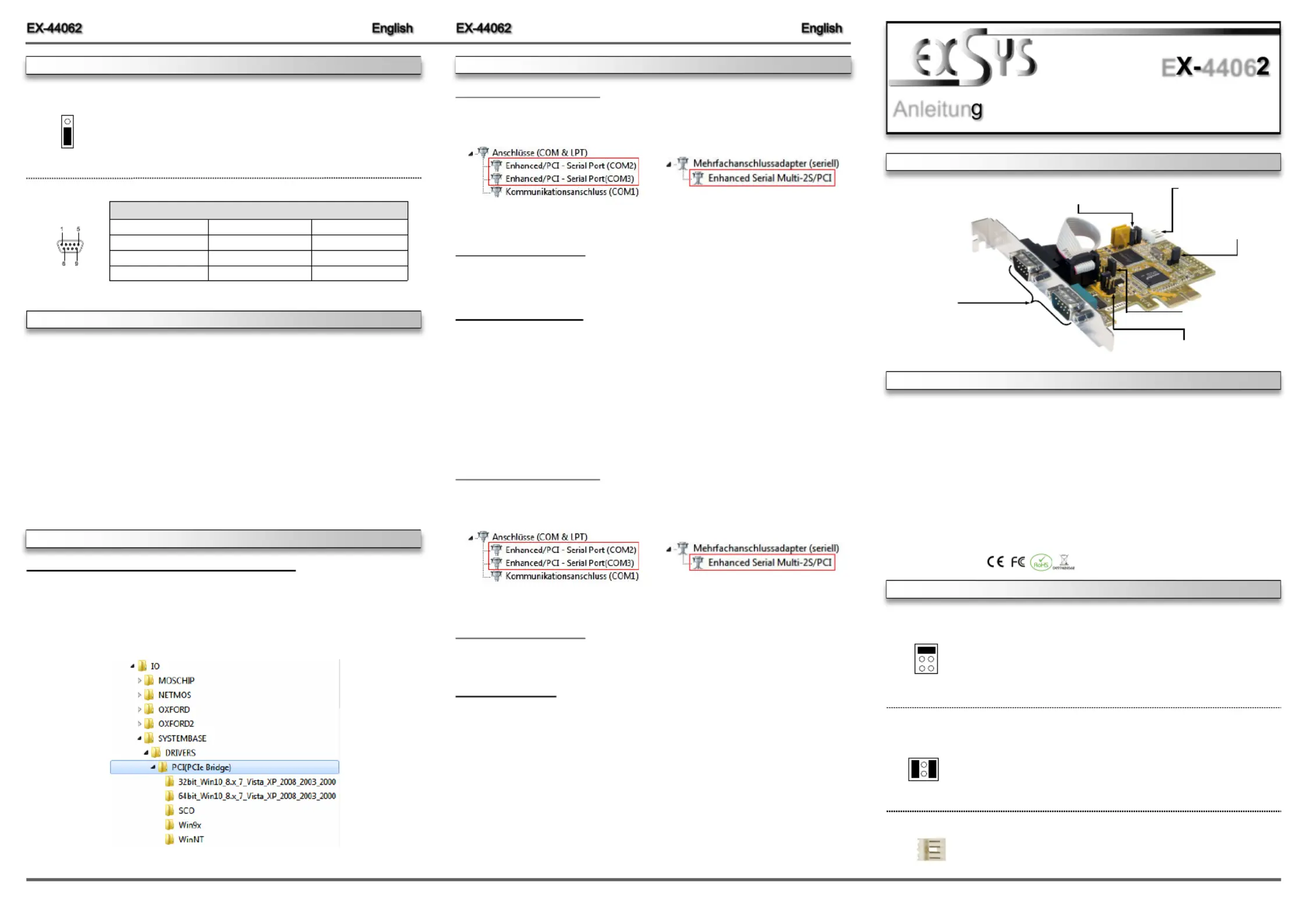
AUFBAU
DRIVER INSTALLATION
Kompatibilität:PCIExpress p1-x1 bis x16-
Betriebssysteme:Windows NT 4.0/ 9x/ 2000/ XP/ Vista/ 7/ 8.x/ 10/ Server 20xx/ Linux
Anschlüsse:2x 9 Pin Seriell Anschluss, 1x 4 Pin Floppy Anschluss
Lieferumfang:44062, Treiber CD, Anleitung, 2x Low Profile BügelEX-
Zertifikate:
J5: Anschluss für Strom
vom PC Netzteil
JP4: Jumper für die Stromquelle
(Netzteil oder PCIExpress Bus)-
JP1 & JP2: Power auf 9 Pin
Stecker Ein/Aus
JP3:PME
- Ein / Ausschalten
JP5:LPT Ein / Aus
Keine Funktion!
S1 & S2:
9 Pin Stecker
Seriell Anschluss
J5:
1 +5V
2 GND
3 GND
4 +12V
Für AUX Einstellung (JP4) muss J5 mit dem PC Netzteil verbunden
werden! Sonst wird die Karte nicht mit Strom versorgt.
RI =Am Pin 9 liegt das Standard Signal RI (Ring Indicator)
(Werkseinstellung)
5 =Am Pin 9 liegt jetzt eine Spannung von DC5V an
12 =Am Pin 9 liegt jetzt eine Spannung von DC12V an
Die Einstellung der Spannung nehmen Sie mit dem JP4 vor. Dies sollte
aber bei Standard Anwendungen nicht verstellt werden.
JP1 & JP2:
RI
5
12
JP4:
Wenn Sie den Jumper JP1 & JP2 auf 5 oder 12 gesetzt haben, können
Sie mit dem Jumper JP4 den Spannungswert einstellen. Es gibt 3
verschiedene Spannungsquellen.
(Nur in Verbindung mit JP1 & JP2 auf 5 oder 12!!!)
X5 - =5Volt vom PCNetzteil (Werkseinstellung)
X12 - =12Volt vom PCNetzteil
I12(Werkseinstellung) =12Volt vom Mainboard
I12 X12 X5
If you are ready with the jumper settings, please proceed with the following installation instructions.
Because there are large differences between PC’s, we can give you only a general installation
guide. Please refer to your computers reference manual whenever in doubt.’
1.Turn off the power to your computer and any other connected peripherals.
2.Remove the mounting screws located at the rear and/ or sides panels of your Computer and
gently slide the cover off.
3.Locate an available expansion slot and remove its covers from the rear panel of your comput-
er. Make sure it is the right expansion slot for the card (see card description)
4.Align the card with the expansion slot, and then gently but firmly, insert the card. Make sure
the card is seated and oriented correctly. Never insert the card by force!
5.Then connect the card with a screw to the rear panel of the computer case.
6.Gently replace your computer’s cover and the mounting screws.
DB 9M:
Serial 9 Pin DSUB Connector-
PinSignalPinSignalPinSignal
14DTR7RTSCDC
2RXD5GROUND8CTS
3TXD6DSR9 RI
Windows NT 4.0/ 9x/ 2000/ XP/ Vista/ 7/ 8.x/ 10
After completing the hardware installation, the operating system will automatically the card and
install this! If the driver should not be installed automatically, insert the driver CD into you CD-
ROM drive (eg drive D:) and then open the folder „IO/SYSTEMBASE/DRIVERS/PCI(PCIe
Bridge)“. Please select the folder with your operating system and install the driver (see Pic-
ture). Follow the hardware assistant and finish the installation. Restart your PC in Important!
any case after installing the drivers.
JUMPERSETTING & CONNECTORS
HARDWAREINSTALLATION
DRIVER INSTALLATION
DIS =The function PME is disable. (Factory Setting)
ENA= The function PME is enable. Now the card can be activate
the computer through the serial ports.
But this should not be adjusted for standard applications.
ENA | DIS
JP3:
CHECK INSTALLED DRIVER
Open the >Device manager<. Now you should see at and at „Ports (COM & LPT)“
„“Multifunction Adapter the following new entry's:
If you see this or a similar information the device is installed correctly.
CHANGE PORT NUMBER
If you like to change the port number for example COM3 to COM5, open the „Device Manager”
click at „COM3 Settings Advance”,„”and then „”. There you can change between COM3 till
COM256.
Windows Server 20xx
After completing the hardware installation, the operating system will automatically the card and
install this! If the driver should not be installed automatically, insert the driver CD into you CD-
ROM drive (eg drive D:) and then open the folder „IO/SYSTEMBASE/DRIVERS/PCI(PCIe
Bridge)“. Please select the folder with your operating system and install the driver (see Picture).
Follow the hardware assistant and finish the installation. Important! Restart your PC in any
case after installing the drivers.
Use the following driver for the following Windows Server Version.
Windows Server 2003=XP Driver
Windows Server 2008=VISTA Driver
Windows Server 2008R2=Windows 7 Driver
Windows Server 2012=Windows 8.x Driver
Windows Server 2012R2=Windows 10 Driver
CHECK INSTALLED DRIVER
Open the >Device manager<. Now you should see at and at „Ports (COM & LPT)“
„“Multifunction Adapter the following new entry's:
If you see this or a similar information the device is installed correctly.
CHANGE PORT NUMBER
If you like to change the port number for example COM3 to COM5, open the „Device Manager”
click at „COM3 Settings Advance”,„”and then „”. There you can change between COM3 till
COM256.
Linux / SCO Unix
The drivers are located in the following folder on our driver CD:
"IO/SYSTEMBASE/DRIVERS/PCI(PCIe Bridge)/SCO"
Because each individual distribution and kernel version of Linux is different, sadly we cant
provide a installation instruction. Please refer to the installation manual for standard IO ports
from your Unix/Linux version! In some newer versions of Linux the card will even be installed
automatically after starting Linux.
Produktspezifikationen
| Marke: | EXSYS |
| Kategorie: | Nicht kategorisiert |
| Modell: | EX-44062 |
| Breite: | 88 mm |
| Tiefe: | 66 mm |
| Gewicht: | 120 g |
| Produktfarbe: | Black, Stainless steel |
| Zweck: | PC |
| Betriebstemperatur: | 0 - 55 °C |
| Relative Luftfeuchtigkeit in Betrieb: | 5 - 95 % |
| Plug & Play: | Ja |
| Eingebaut: | Ja |
| Temperaturbereich bei Lagerung: | -40 - 75 °C |
| Unterstützt Windows-Betriebssysteme: | Ja |
| Serielle Schnittstelle: | RS-232 |
| Nachhaltigkeitszertifikate: | RoHS |
| Unterstützte Linux-Betriebssysteme: | Ja |
| Anzahl serielle Anschlüsse: | 2 |
| Hostschnittstelle: | PCIe |
| RS232: | Ja |
| Ausgangsschnittstelle: | Seriell |
| Datenbits: | 5, 6,7, 8 |
| FIFO (First In, First Out): | 256 B |
| Stop bits: | 1, 1.5, 2 |
| Formfaktor der Erweiterungskarte: | Niedriges Profil |
Brauchst du Hilfe?
Wenn Sie Hilfe mit EXSYS EX-44062 benötigen, stellen Sie unten eine Frage und andere Benutzer werden Ihnen antworten
Bedienungsanleitung Nicht kategorisiert EXSYS

14 März 2026
26 September 2025
26 September 2025
6 September 2025
6 September 2025
5 September 2025
31 Juli 2025
25 Juli 2025
24 Juli 2025
24 Juli 2025
Bedienungsanleitung Nicht kategorisiert
Neueste Bedienungsanleitung für -Kategorien-
3 April 2026
3 April 2026
3 April 2026
3 April 2026
3 April 2026
3 April 2026
3 April 2026
3 April 2026
3 April 2026
3 April 2026