Festo DYSD-Q11-12-12-Y1F-Y9 Bedienungsanleitung
Festo Nicht kategorisiert DYSD-Q11-12-12-Y1F-Y9
Lies die bedienungsanleitung für Festo DYSD-Q11-12-12-Y1F-Y9 (2 Seiten) kostenlos online; sie gehört zur Kategorie Nicht kategorisiert. Dieses Handbuch wurde von 8 Personen als hilfreich bewertet und erhielt im Schnitt 4.8 Sterne aus 5 Bewertungen. Hast du eine Frage zu Festo DYSD-Q11-12-12-Y1F-Y9 oder möchtest du andere Nutzer dieses Produkts befragen? Stelle eine Frage
Seite 1/2
DYSD
Shock absorber
Festo SE & Co. KG
Ruiter Straße 82
73734 Esslingen
Deutschland
+49 711 347-0
www.festo.com
Operating instructions
8168633
2022-02
[8168635]
Translation of the original instructions
© 2022 all rights reserved to Festo SE & Co. KG
1
Applicable documents
All available documents for the product
è
www.festo.com/sp.
DocumentsProductContents
Operating instructionsSemi-rotary drive DRRD–
Tab. 1:
Applicable documents
2
Safety
2.1Safety instructions
–
Only use the product in its original condition without unauthorised modifica-
tions.
–Observe the identifications on the product.
–
Store the product in a cool, dry environment protected from UV and corrosion.
Keep storage times short.
–Repair of the product is not permitted.
–
Before working on the product, switch off the compressed air supply and lock it
to prevent it from being switched on again.
2.2Intended use
The product is intended for use in the pressure chamber for cushioning the force
with rotary moving masses in an axial direction.
2.3
Training of qualified personnel
Work on the product may only be carried out by qualified personnel who can eval-
uate the work and detect dangers. Personnel must have the relevant mechanical
training.
3Additional information
–Contact the regional Festo contact if you have technical problems
è
www.festo.com.
–
Accessories and spare parts
è
www.festo.com/catalogue.
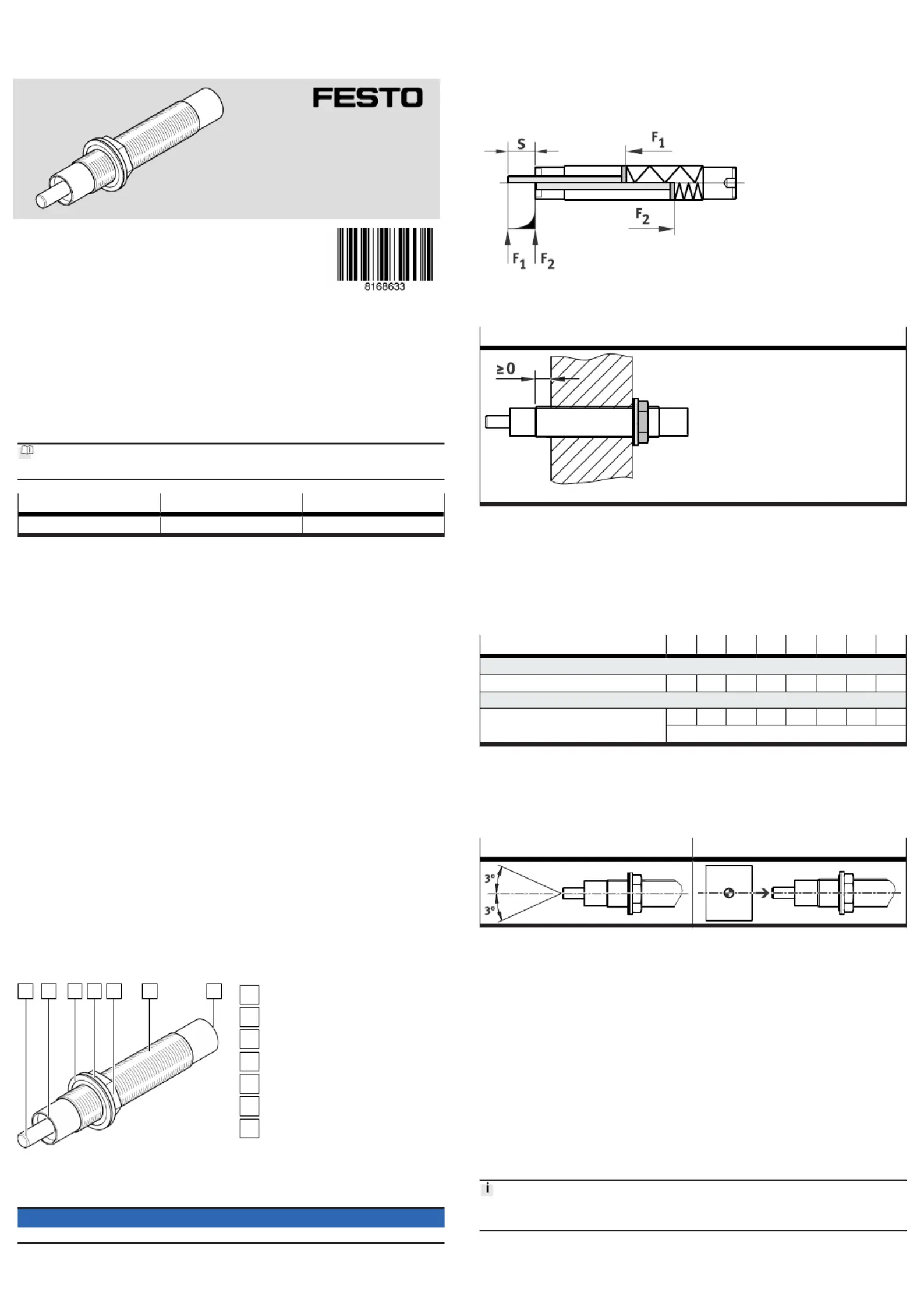
4Product overview
4.1Product design
1235674
Fig. 1:
Product design
1
Piston rod
2
(Fixed) stop
3
Sealing washer
4
Disc
5
Lock nut
6
Male thread
7
Internal hexagon
The screw in the internal hexagon socket of the shock absorber must not be
loosened.
NOTICE
Tensile forces on the piston rod can seriously damage the shock absorber.
4.2Function
Insertion force F2 acting on the buffer moves the piston rod of the hydraulic shock
absorber through the cushioning length s to the fixed stop to the end position.
When the piston rod is retracted, the hydraulic fluid in the shock absorber flows
through a path-dependent flow control valve and cushions the motion.
If the insertion force is less than the reset force F1 of the internal compression
spring, the piston rod returns to the initial position.
F1Reset force
F2Insertion force
sStroke/cushioning distance
Tab. 2:Function
5
Mounting product
Lock nut mounting on one side
The mounting surface must not protrude beyond the thread area.
Tab. 3:Mounting in thread
1.
Screw in the product up to the intended stop position.
The order of installation of the washer and sealing washer must be followed
to guarantee a tight seal to the pressure chamber (lock nut, washer, sealing
washer).
Do not exceed the maximum torque when screwing or holding the internal
hexagon socket/slot.
2.
Tighten the lock nut to the tightening torque.
DYSD-...-5-7-8-12-16-20-25-32
Internal hexagon/slot
Max. torque[Nm]0.51.53612202550
Lock nut
Tightening torque[Nm]23520356080100
Tolerance ± 20%
Tab. 4:
Torques
5.1Aligning product
–Observe the axial direction of force of the moving mass to the axis of the shock
absorber.
–The mass must contact the piston rod and the fixed stop over a wide area.
Force direction, max. deviationAlignment of the mass
Tab. 5:
Permissible axial force direction and alignment of the moving mass
6Commissioning
6.1Executing test run
1.Start the test run at the drive at reduced velocity.
2.
If necessary, readjust the position of the shock absorber.
3.Gradually increase the velocity of the drive to the operating value in steps.
Ä
If set correctly, the end position is reached without a hard stop.
With hard stop:
–
Reduce the impact velocity if necessary.
–Check function and design of the shock absorber.
6.2Notes on operation
Energy absorption
•Only use the shock absorber within the permissible range of 25 % … 100 % of
the maximum energy absorption
è
10 Technical data.
Recommendation: use the shock absorber within the optimum range from
50 % … 80 % of the maximum energy absorption.
Produktspezifikationen
| Marke: | Festo |
| Kategorie: | Nicht kategorisiert |
| Modell: | DYSD-Q11-12-12-Y1F-Y9 |
Brauchst du Hilfe?
Wenn Sie Hilfe mit Festo DYSD-Q11-12-12-Y1F-Y9 benötigen, stellen Sie unten eine Frage und andere Benutzer werden Ihnen antworten
Bedienungsanleitung Nicht kategorisiert Festo

1 August 2025
1 August 2025
1 August 2025
1 August 2025
1 August 2025
1 August 2025
1 August 2025
1 August 2025
1 August 2025
1 August 2025
Bedienungsanleitung Nicht kategorisiert
Neueste Bedienungsanleitung für -Kategorien-
3 April 2026
3 April 2026
3 April 2026
3 April 2026
3 April 2026
3 April 2026
3 April 2026
3 April 2026
3 April 2026
3 April 2026