Hager H400NE-400A3P Bedienungsanleitung
Hager Nicht kategorisiert H400NE-400A3P
Lies die bedienungsanleitung für Hager H400NE-400A3P (2 Seiten) kostenlos online; sie gehört zur Kategorie Nicht kategorisiert. Dieses Handbuch wurde von 27 Personen als hilfreich bewertet und erhielt im Schnitt 4.4 Sterne aus 6 Bewertungen. Hast du eine Frage zu Hager H400NE-400A3P oder möchtest du andere Nutzer dieses Produkts befragen? Stelle eine Frage
Seite 1/2
10
mm
M type
M Type B Type
T2AX00M T2AX00B
T2AL00M T2AL00B
T2SH00 T2UV00
Alarm Switch
M Type B Type
Shunt Trip
Undervoltagie Trip
Auxiliary Switch
Innovators in Protection Technology
2G0774SAA (KRB-0532)
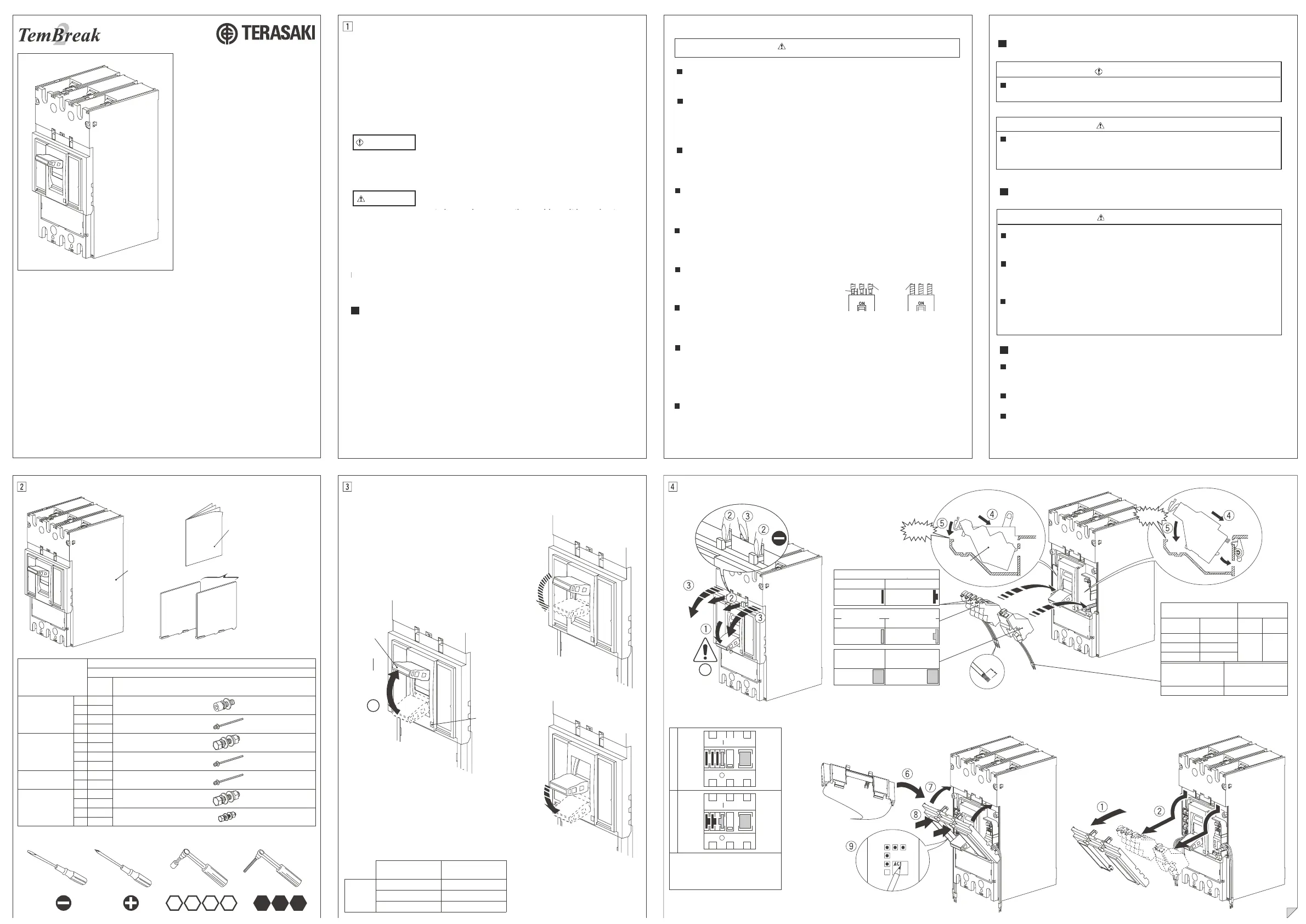
Instruction Manual for
Moulded Case Circuit
Breakers
Types
H400-NE
L400-NE
Packaged Items/Assembly ToolsOperating InstructionsFitting Internal Accessories
Symbols of Accessories
Ring Mark
Breaker:1
Instruction
3P: 2
4P: 3
Instruction Manual:1
(This document)
Interpole Barrier
(Only FC)
865
19171310
RESET
TRIPPED
OFF
Slits of pulling out leads
AX
AL
SH
UV
V
Removal
Pull Out Leads on Load Side
Combination
After fitting, verify the function of the Accessory.
Handle
Trip Button
ON
OFF
B Type M Type
In case of fitting one(or two) auxiliary
switch, fit in an order from a left side-
slot.
ON
OFF
ON
OFF
Connections/Poles
Type
400AF
Qty
H400-NE
L400-NE
FC
Front
Connected
3P
6
M10×30
4P
8
3P
4
M6×140
4P
4
RC
Rear
Connected
3P
6
M12×35
4P
8
3P
4
M6×140
4P
4
3P
4
M6×160
4P
4
F.P
Flush Plate
Where Applicable
3P
6
M12×35
4P
8
3P
4
M6×25
4P
4
Auxiliary SwitchAlarm Switch
a contactb contact
a contactb contact
11/AXc-14/AXa11/AXc-12/AXb
91/ALc
-
94
/
ALa
91/ALc
-
92
/
ALb
21/AXc-24/AXa21/AXc-22/AXb
31/AXc-34/AXa31/AXc-32/AXb
Shunt Trip
power source
C1-C2
Undervoltage Trip
power source
D1-D2
PM
Plug-in Connected
Please retain this manual for future reference.The Manufacturer assumes no
responsibility for damages resulting from non-application or incorrect application of the
instructions provided herein.
interpole
barriers
insulating tubes
or
insulating tape
OperationOperation effort
H400-NE
L400-NE
○(OFF)(ON)
110N
(ON)○(OFF)
115N
TRIP○(OFF)
125N
TERASAKI ELECTRIC (EUROPE) LTD.
80 Beardmore Way
Clydebank Industrial Estate
Clydebank, G81 4HT, SCOTLAND
Tel: +44 (0) 141 941 1940
Fax: +44 (0) 141 952 9246
www.terasaki.com
Be sure to read these instructions and other documents accompanying this
product. Please familiarise yourself with handling of this product, safety
information, and all other precautions before mounting, using, servicing or
inspection. In these instructions, safety notices are divided into "Warning"
and "Caution" according to the hazard level.
neglecting the suggested procedure or practice could result in lethal or
serious personal injury.
neglecting the suggested procedure or practice could result in moderate
or slight personal injury and/or property damage.
A warning notice with this symbol indicates that
For detailed mounting dimensions, refer to the TemBreak 2 catalogue.
A caution notice with this symbol indicates that
Safety Notices
Mounting Precautions
WARNING
CAUTION
CAUTION
Note that failing to observe
results in some cases. Because safety notices contain important information,
be sure to read and observe them.
notices could result in serious
Electrical work should only be undertaken by suitably qualified
persons.
Do not place the product an an area that is subject to high temperature,
high humidity, excessive dust air, corrosive gas, strong vibration and
shock, or other unusual conditions. Mounting in such areas could cause
a fire or malfunction.
Be careful to prevent foreign objects (debris, concrete, iron powder etc)
and rainwater from entering product. These materials inside the product
could cause a fire or malfunction.
Prior to commencing any work on the product, open an upstream circuit
breaker or isolator to ensure that no voltage is applied to the product
otherwise electrical shock may result.
For 4 pole breakers, be sure to connect a neutral conductor to the
N-phase pole, otherwise an overcurrent may hinder the product from
tripping thus resulting in a fire.
When connecting cable or busbar to the product, tighten terminal screws
to the torque specified in this manual,
otherwise, a fire could result.
After conductor connection, do not
apply excessive force to the terminals.
Otherwise, a fire may result.
For front-connected breakers, insulate all bare conductors of the line side
until the breaker end. If interpole barriers are packed, be sure to use the
barriers; moreover, insulate all bare conductors by insulting tape or the
like so that the tape overlaps with the barriers. Insufficient insulation may
result in short-circuit.
Do not block the arc gas vents of the product to ensure adequate arc space.
Blocking these vents could result in failure of circuit interruption.
CAUTION
Handling Precautions
Maintenance Precautions
Other Precautions
Never touch terminals. Otherwise, electric shock may result
When the breaker trips open automatically, remove the cause, then
return the handle to the ON position. Should a fault be interrupted,
the breaker must be inspected, otherwise, a fire may result.
Service and/or inspection of the product must be done by persons
having expert knowledge.
Before servicing or inspecting the product, open an upstream circuit
breaker or the like to isolate all sources of power. Otherwise, electric
shock may result.
Regularly check that the breaker terminal screws are tightened to
torque values shown within this manual, failure to do so may result
in fire.
Do not carry this product by accessory leads, as this may cause damage
to the product.
Unauthorised opening of the breaker cover will invalidate product warranty.
When installing the product, use wires or conductors, the cross sectional
areas of which accommodate the rated current of the product. Using wires
or conductors with inadequate cross sectional areas may cause false
tripping and overheat.
CAUTION
CAUTION
WARNING
**
**
**
*
10
mm
M形
M type
M Type
B Type
M Type
B Type
T2AX00M
T2AL00M
T2SH00T2UV00
Alarm Switch
Shunt Trip
Undervoltage Trip
**
**
**
Auxiliary Switch
T2AX00B
T2AL00B
Innovators in Protection Technology
2G0331SAJ(KRB-0335j)
Types
Fixed Types
S50-GF
S100-NFS100-GFH100-NFL100-NF
E225-NFS225-NFS225-GFH225-NF
L225-NFS125-NFS125-GFH125-NF
L125-NFE250-NFS250-NFS250-GF
H250-NFL250-NF
(Adjustable Thermal Magnetic Types)
E125-NJS125-NJS125-GJH125-NJL125-NJ
S160-NJH160-NJL160-NJ
E250-NJS250-NJS250-GJH250-NJL250-NJ
S225-GES225-PEH225-NES250-PEH250-NE
Instruction Manual for Moulded
Case Circuit Breakers
Packaged Items/Assembly Tools
*Symbols of Accessories
Ring Mark
Breaker: 1
Instruction
2P:1
3P:2
4P:3
Instruction Manual: 1
(This document)
Interpole Barrier
(Only FC)
48
101713
56
RESET
TRIPPED
(OFF)
・
(ON)
Handle
(OFF)
Trip Button
Removal
AX
AL
SH
UV
V
f
g
h
i
f
g
h
i
the grooves carved
on the back.
Pull Out Leads on Load SideCombination
In case of tting only one auxiliary
switch, t in left side slot.
Type1
Type2,Type3,Type4
B Type M Type
(ON)
(OFF)
(ON)
(OFF)
(ON)
(OFF)
(ON)
(OFF)
Auxiliary SwitchAlarm Switch
a contactb contact
a contactb contact
11/AXc-14/AXa11/AXc-12/AXb
91/ALc-
94/ALa
91/ALc-
92/ALb
21/AXc-24/AXa21/AXc-22/AXb
Shunt Trip
power source
C1-C2
Undervoltage Trip
power source
D1-D2
Please retain this manual for future reference. The Manufacturer assumes
no responsibility for damages resulting from non-application or incorrect
application of the instructions provided herein.
Operation
Type1
(OFF)|(ON)
22N
(OFF)|(ON)
25N
|(ON)(OFF)
28N
TRIP(OFF)
68N
Type2
Type3
Type4
|(ON)(OFF)
36N
TRIP(OFF)
76N
Connections/Poles
Type
Type 1
Qty
S50-GF S100
E125S125
(FC)
Front
Connected
2P
4
a:M8×16
3P
6
4P
8
2P
2
2P
2
b:M4×80
3P
2
PMB)
Plug-in
Connected
50/ 100/ 125AF
Type 2Type 3Type 4
100/ 125AF160/ 225/ 250AF160/ 225/ 250AF
Qty
H100L100
H125L125
Qty
S160E225S225
E250S250
Qty
H160L160H225
L225H250L250
d:M8×20d:M8×20d:M8×20
666
888
b:M4×115b:M4×80b:M4×115
424
b:M4×55b:M4×90b:M4×55b:M4×90
3P
2222
4P
4444
(RC)
Rear
Connected
2P
4
c:M8×25c:M8×25c:M8×25c:M8×25
3P
6666
4P
8888
2P
2
b:M4×55b:M4×90b:M4×55b:M4×90
3P
2222
4P
4444
4P
4444
(F.P)
Flush Plate
Where
Applicable
2P
4
c:M8×25c:M8×25c:M8×25c:M8×25
3P
6666
4P
8888
2P
4
e:M5×16e:M5×16e:M5×16e:M5×16
3P
4444
4P
4444
:e:d:c:b:a
(PMC)
Plug-in
Connected
3P
2
b:M4×58
4
b:M4×100
2
b:M4×65
4
b:M4×100
Be sure to read these instructions and other documents accompanying this
product. Please familiarise yourself with handling of this product, safety
information, and all other precautions before mounting, using, servicing or
inspection. In these instructions, safety notices are divided into "Warning"
and "Caution" according to the hazard level.
neglecting the suggested procedure or practice could result in lethal or
serious personal injury.
neglecting the suggested procedure or practice could result in moderate
or slight personal injury and/or property damage.
A warning notice with this symbol indicates that
For detailed mounting dimensions, refer to the TemBreak 2 catalogue.
A caution notice with this symbol indicates that
Safety Notices
Mounting Precautions
WARNING
CAUTION
CAUTION
Note that failing to observe
results in some cases. Because safety notices contain important information,
be sure to read and observe them.
notices could result in serious
Electrical work should only be undertaken by suitably qualified
persons.
Do not place the product an an area that is subject to high temperature,
high humidity, excessive dust air, corrosive gas, strong vibration and
shock, or other unusual conditions. Mounting in such areas could cause
a fire or malfunction.
Be careful to prevent foreign objects (debris, concrete, iron powder etc)
and rainwater from entering product. These materials inside the product
could cause a fire or malfunction.
Prior to commencing any work on the product, open an upstream circuit
breaker or isolator to ensure that no voltage is applied to the product
otherwise electrical shock may result.
For 4 pole breakers, be sure to connect a neutral conductor to the
N-phase pole, otherwise an overcurrent may hinder the product from
tripping thus resulting in a fire.
When connecting cable or busbar to the product, tighten terminal screws
to the torque specified in this manual,
otherwise, a fire could result.
After conductor connection, do not
apply excessive force to the terminals.
Otherwise, a fire may result.
For front-connected breakers, insulate all bare conductors of the line side
until the breaker end. If interpole barriers are packed, be sure to use the
barriers; moreover, insulate all bare conductors by insulting tape or the
like so that the tape overlaps with the barriers. Insufficient insulation may
result in short-circuit.
Do not block the arc gas vents of the product to ensure adequate arc space.
Blocking these vents could result in failure of circuit interruption.
CAUTION
Handling Precautions
Maintenance Precautions
Other Precautions
Never touch terminals. Otherwise, electric shock may result
When the breaker trips open automatically, remove the cause, then
return the handle to the ON position. Should a fault be interrupted,
the breaker must be inspected, otherwise, a fire may result.
Service and/or inspection of the product must be done by persons
having expert knowledge.
Before servicing or inspecting the product, open an upstream circuit
breaker or the like to isolate all sources of power. Otherwise, electric
shock may result.
Regularly check that the breaker terminal screws are tightened to
torque values shown within this manual, failure to do so may result
in fire.
Do not carry this product by accessory leads, as this may cause damage
to the product.
Unauthorised opening of the breaker cover will invalidate product warranty.
When installing the product, use wires or conductors, the cross sectional
areas of which accommodate the rated current of the product. Using wires
or conductors with inadequate cross sectional areas may cause false
tripping and overheat.
CAUTION
CAUTION
WARNING
[1]
TERASAKI ELECTRIC (EUROPE) LTD.
80 Beardmore Way
Clydebank Industrial Estate
Clydebank, G81 4HT, SCOTLAND
Tel: +44 (0) 141 941 1940
Fax: +44 (0) 141 952 9246
www.terasaki.com
[2]
Operating Instructions
[3]
Fitting Internal Accessories
[4]
Montageanleitung für
geschlossene
Leistungsschalter
Sicherheitshinweise
Lieferumfang / MontagewerkzeugeBetriebsanleitungInterne Zubehörteile einbauen
Sicherheitsmaßnahmen bei der Handhabung
Sicherheitsmaßnahmen bei der Wartung
Weitere Sicherheitsvorschriften
Sicherheitshinweise für die Montage
Ausführungen
Bitte bewahren Sie diese Montageanleitung zur späteren Verwendung auf.
Der Hersteller übernimmt keinerlei Verantwortung für Schäden, die durch
Nichtbeachtung oder falsche Umsetzung der Anweisungen in dieser Anleitung
entstehen.
Lesen Sie diese Anleitung sowie alle weiteren dem Produkt beiliegenden
Dokumente aufmerksam durch. Machen Sie sich vor Montage, Gebrauch,
Wartung oder Prüfung des Produkts mit dessen Handhabung, den Sicher-
heitshinweisen sowie allen anderen Sicherheitsvorschriften vertraut. In dieser
Anleitung wird bei den Sicherheitshinweisen je nach Gefährdungsgrad unter-
schieden zwischen „Vorsicht“ und „Achtung“.
Arbeiten an elektrischen Anlagen dürfen ausschließlich von qualizierten
Fachkräften durchgeführt werden.
Das Produkt darf weder hohen Temperaturen, hoher Luftfeuchtigkeit, Luft
mit hohem Staubanteil, korrosiven Gasen, starken Vibrationen oder Stößen
oder sonstigen außergewöhnlichen Belastungen ausgesetzt werden. Eine
Montage unter solchen Bedingungen kann Fehlfunktionen oder Brände
verursachen.
Sicherstellen, dass keine Fremdkörper (z.B. Schmutzpartikel, Zement,
Eisenpulver) und Regenwasser in das Produkt eindringen. Solche
Fremdkörper im Produkt können Brände oder Fehlfunktionen verursachen.
Vor der Durchführung jedweder Arbeiten am Produkt muss die
vorgeschaltete Sicherung bzw. der vorgeschaltete Leistungsschalter
geöffnet werden, um die Spannungsfreiheit des Produkts sicherzustellen.
Andernfalls besteht die Gefahr eines elektrischen Schlags.
Bei 4-poligen Leistungsschaltern muss unbedingt ein Neutralleiter an den Pol
der N-Phase angeschlossen werden. Andernfalls kann durch Überstrom das
Auslösen des Produkts verhindert werden. Dies kann Brände verursachen.
Beim Anschließen von Kabeln oder Stromschiene an das Produkt
Zur Sicherstellung eines ausreichenden Raums für den Funkenüberschlag
dürfen die Funkengasöffnungen nicht verschlossen werden.
Das Verschließen dieser Öffnungen kann zu einem Ausfall der Stromkreis-
unterbrechung führen.
müssen die Klemmenschrauben mit dem in dieser Montageanleitung
vorgeschriebenen Drehmoment festgezogen
werden. Andernfalls können Brände entstehen.
Das Signalwort „Vorsicht“ und das Symbol weisen
Das Signalwort „Achtung“ und das Symbol weisen
Die Montagemaße nden Sie im Katalog TemBreak 2.
darauf hin, dass bei Nichtbeachtung der vorgeschriebenen Vorgehens-
weise die Gefahr von schweren Verletzungen und Verletzungen mit
Todesfolge besteht
darauf hin, dass bei Nichtbeachtung der vorgeschriebenen Vorgehens-
weise die Gefahr von mittelschweren oder leichten Verletzungen bzw.
Sachschäden besteht.
VORSICHT
ACHTUNG
ACHTUNG
Nach Anschluss der Leiter dürfen keine
übermäßigen Kräfte auf die Klemmen einwir-
ken. Andernfalls können Brände entstehen.
Bei Leistungsschaltern mit Frontanschluss müssen freiliegende Leiter bis zu
den Leistungsschalteranschlüssen isoliert werden. Falls Phasentrennwände
mitgeliefert wurden, müssen diese unbedingt montiert werden. Außerdem
müssen alle exponierten Leiter so weit isoliert werden, bis die Isolierung die
Phasentrennwände überlappt. Eine unzureichende Isolierung kann zu Kurz-
schlüssen führen.
Phasen-
trenn-
wände
Isolier-
schläuche
oder
-band
ACHTUNG
ACHTUNG
VORSICHT
Niemals die Klemmen berühren. Stromschlaggefahr!
Wartungs- und Prüfarbeiten am Produkt dürfen ausschließlich von
qualizierten Fachkräften durchgeführt werden.
Produkt nicht an den Zubehörkabel anheben, dies kann Schäden am
Produkt verursachen.
Unbefugtes Öffnen des Leistungsschalters führt zum Erlöschen der
Produktgarantie.
Beim Einbau des Produkts nur Drähte und Leiter mit einem für den
Bemessungsstrom des Produkts ausreichenden Querschnitt verwenden.
Die Verwendung von Drähten oder Leitern mit ungenügendem Querschnitt
kann Auslösefehler und Überhitzung verursachen.
Vor dem Durchführen von Wartungs- und Prüfarbeiten am
Produkt den vorgeschalteten Leistungsschalter oder vergleichbare
Einrichtung öffnen, um sämtliche Stromquellen zu trennen.
Andernfalls besteht Stromschlaggefahr.
Klemmenschrauben des Leistungsschalters regelmäßig auf das in
dieser Montageanleitung angegebene Drehmoment prüfen.
Andernfalls besteht Brandgefahr.
Wenn der Leistungsschalter automatisch auslöst, die Ursache beheben
und dann den Kipphebel zurück auf EIN stellen. Im Auslösefall muss der
Leistungsschalter geprüft werden, andernfalls besteht Brandgefahr.
Leistungsschalter: 1
Montageanleitung: 1
(Dieses Dokument)
Montage-
anleitung
Phasentrennwand
(Nur Frontanschluss)
Anschlüsse / Pole
Ausführung
Funktion
Betätigungskraft
Kombination
M Ausführung
B Ausführung
AUSGELÖST
Anz.
Kipphebel
Auslösetaste
RÜCKSTELLUNG
(EIN)
(AUS)
(AUS)
(AUS)
(AUS)
(AUS)
(EIN)
(EIN)
(EIN)
(EIN)
(AUS)
(AUS)
AUS-
LÖSUNG
Falls nur ein Hilfsschalter verbaut werden
soll, muss dieser in den linken Schacht
eingebaut werden.
Funktion der Zubehörteile nach dem Einbau prüfen.
Klick!
Klick!
Hilfsschalter
Alarmhilfsschalter
M Ausführung
M Ausführung
Arbeitsstrom-
auslöser
B Ausführung
B Ausführung
Unterspannungs-
auslöser
Symbole der Zubehörteile
Kabel auf Lastseite herausziehen
Öffnung für Steuerverdrahtung
Ringmarkierung
Hilfsschalter
Arbeitsstromauslöser
Stromquelle
Unterspannungsauslöser
Stromquelle
Alarmhilfsschalter
a Kontakt
a Kontakt
b Kontakt
b Kontakt
Ausbau
Front-
anschluss
Stecksockelanschluss
Abdeckplatte
(wo zutreffend)
Rück-
anschluss
Die Nichtbeachtung von Hinweisen mit dem Signalwort „Achtung“ kann
schwerwiegende Folgen haben. Sicherheitshinweise enthalten wichtige
Informationen. Lesen Sie diese deshalb gründlich durch und beachten
Sie sie zu jeder Zeit.
Produktspezifikationen
| Marke: | Hager |
| Kategorie: | Nicht kategorisiert |
| Modell: | H400NE-400A3P |
Brauchst du Hilfe?
Wenn Sie Hilfe mit Hager H400NE-400A3P benötigen, stellen Sie unten eine Frage und andere Benutzer werden Ihnen antworten
Bedienungsanleitung Nicht kategorisiert Hager

27 September 2025
27 September 2025
26 September 2025
26 September 2025
26 September 2025
26 September 2025
26 September 2025
26 September 2025
26 September 2025
26 September 2025
Bedienungsanleitung Nicht kategorisiert
Neueste Bedienungsanleitung für -Kategorien-
28 Februar 2026
28 Februar 2026
28 Februar 2026
28 Februar 2026
28 Februar 2026
28 Februar 2026
28 Februar 2026
28 Februar 2026
28 Februar 2026
28 Februar 2026