INFICON VSD200 Bedienungsanleitung
INFICON Nicht kategorisiert VSD200
Lies die bedienungsanleitung für INFICON VSD200 (2 Seiten) kostenlos online; sie gehört zur Kategorie Nicht kategorisiert. Dieses Handbuch wurde von 7 Personen als hilfreich bewertet und erhielt im Schnitt 4.3 Sterne aus 7 Bewertungen. Hast du eine Frage zu INFICON VSD200 oder möchtest du andere Nutzer dieses Produkts befragen? Stelle eine Frage
Seite 1/2
Vacuum Switch
VSA200, VSD200
Operating Manual
Incl. EU Declaration of Conformity
tina65e1-b (2016-10)
Product Identification
In all communications with INFICON, please specify the in-
formation on the product nameplate. For convenient refe-
rence copy that information into the space provided below.
Model:
Set point:
PN:
SN:
V W
LI-9496 Balzers
Validity
This document applies to products with the following part
numbers:
VSA200
3SA1-xxx-xxxx
Set-point value
F5
1000
Torr
G6
1100 mbar
Unit
Flange
0
Standard
R
Inverted
H
High Trip Point
Configuration
1 DN 16 ISO-KF
C
4 VCR male
D
4 VCR female
VSD200
3SD1-Mxx-xxxx
Set-point value
Flange
1
DN 16 ISO-KF
C
4 VCR male
D
4 VCR female
A
+
B –
Sign
5
Torr
6
mbar
Unit
0 Standard
R
Inverted
H
High Trip Point
Configuration
The part number (PN) can be taken from the product name-
plate.
If not indicated otherwise in the legends, the illustrations in
this document correspond to the vacuum switch with vacuum
connection DN 16 ISO-KF. They apply to vacuum switches
with other vacuum connection by analogy.
We reserve the right to make technical changes without prior
notice.
All dimensions in mm.
Intended Use
The vacuum switches have been designed for the use in
vacuum systems as absolute pressure switch (VSA200) or as
differential pressure switch (VSD200) in different measure-
ment ranges.
Trademark
VCR
®
Swagelok Marketing Co.
Safety
Symbols Used
DANGER
Information on preventing any kind of physical injury.
WARNING
Information on preventing extensive equipment and envi-
ronmental damage.
Caution
Information on correct handling or use. Disregard can lead
to malfunctions or minor equipment damage.
Personnel Qualifications
Skilled personnel
All work described in this document may only be carried out
by persons who have suitable technical training and the
necessary experience or who have been instructed by the
end-user of the product.
General Safety Instructions
•Adhere to the applicable regulations and take the nec-
essary precautions for the process media used.
Consider possible reactions between the materials and the
process media.
•Adhere to the applicable regulations and take the neces-
sary precautions for all work you are going to do and con-
sider the safety instructions in this document.
•Before beginning to work, find out whether any vacuum
components are contaminated. Adhere to the relevant re-
gulations and take the necessary precautions when hand-
ling contaminated parts.
Communicate the safety instructions to all other users.
Liability and Warranty
INFICON assumes no liability and the warranty becomes null
and void if the end-user or third parties
•disregard the information in this document
•use the product in a non-conforming manner
•make any kind of interventions (modifications, alterations
etc.) on the product
•use the product with accessories not listed in the product
documentation.
The end-user assumes the responsibility in conjunction with
the process media used.
Gauge failures due to contamination or wear and tear, are not
covered by the warranty.
Technical Data
Measurement range
VSA200 (absolute)
1100 mbar (F.S.)
1000 Torr (F.S.)
VSD200 (relative to atm) -100 … +50 mbar, Torr
Setpoint (setting range)
VSA200
30 … 1060 mbar
20 … 970 Torr
VSD200 -99 … +46 mbar, Torr
Switching contact changeover contact, floating
Hysteresis 2 % F.S. above setpoint
Contact rating
Switching
characteristics
1)
≤30 V (dc) / 1 A (dc)
≤30 V (ac) / 0.3 A (ac)
Low Trip Point
Accuracy ≤0.5 % F.S.
Resolution 10 bit
Switching frequency 0.5 Hz
Response time ≤45 ms
Temperature effect on zero
and span
≤±0.02 % F.S. / 1K
Long-term stability ≤±0.5 % F.S. / a
Effect supply voltage ≤±0.005 % F.S. / V
Starting time 1 s
Service live
Electronic
Relay
>1×10
8
cycles
25'000 h
>3×10
6
cycles
Supply
DANGER
The vacuum switch may only be connected to
power supplies, instruments or control devices
that conform to the requirements of a grounded
extra-low voltage (PELV). The connection to the
vacuum switch has to be fused.
Supply voltage +14 … +30 V (dc)
Current consumption ≤15 mA
Power consumption ≤0.5 W
Electrical connection D-Sub, 9 pin, male
Cable 6 pin plus shielding
Cable length ≤100 m (8×0.14 mm
2
)
Materials exposed to
vacuum
Housing
Diaphragm
1.4571, 1.4404
1.4435
Internal volume
DN 16 ISO-KF
4 VCR
®
2.81 cm
3
0.93 cm
3
Admissible pressure (abs.)
VSA200
VSD200
5 bar
2 bar
Admissible temperatures
Operation
Storage
0 … +70 °C
–40 … +80
Relative humidity ≤80 at temperatures up to
≤+31 °C, decreasing to 50
at +40 °C
Use indoors only, altitude up to
4000 m NN
Mounting orientation any
Degree of protection IP40
1)
The switching characteristics and the setpoint can be
programmed via the serial interface (pin 6, 7, 8).
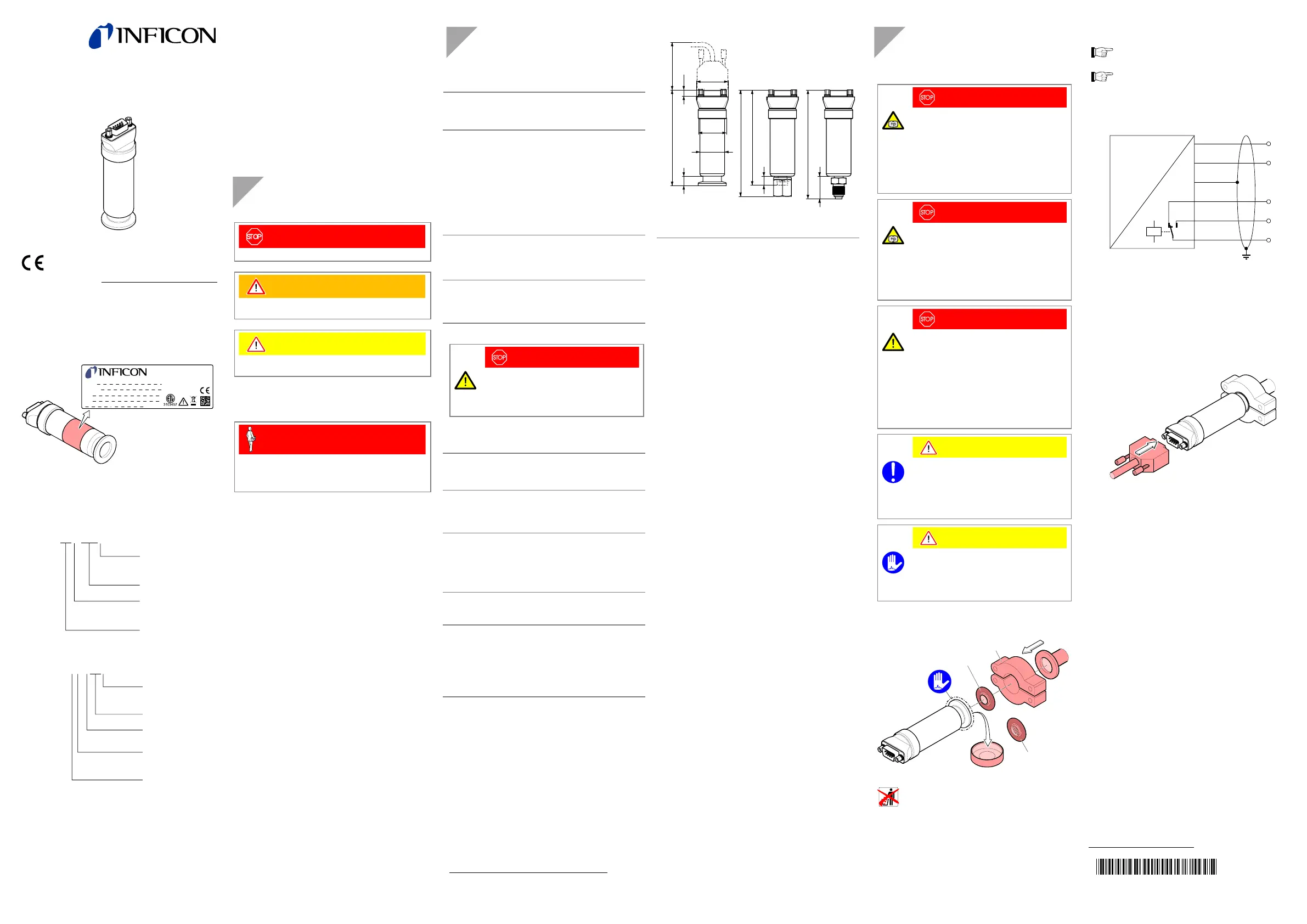
Dimensions [mm]
DN 16 ISO-KF
101.5
≈60
10
ø30
ø26.5
34
4 VCR
female
4 VCR
male
24.2
117
9
5.5
104.5
117.5
Weight
≈140 g
Installation
Vacuum Connection
DANGER
DANGER: overpressure in the vacuum system
>1 bar
Injury caused by released parts and harm
caused by escaping process gases can result if
clamps are opened while the vacuum system is
pressurized.
Do not open any clamps while the vacuum sys-
tem is pressurized. Use the type of clamps which
are suited to overpressure.
DANGER
DANGER: overpressure in the vacuum system
>2.5 bar
KF connections with elastomer seals (e.g.
O-rings) cannot withstand such pressures. Pro-
cess media can thus leak and possibly damage
your health.
Use O-rings provided with an outer centering
ring.
DANGER
DANGER: protective ground
Incorrectly grounded products can be extremely
hazardous in the event of a fault.
The gauge must be electrically connected to the
grounded vacuum chamber. This connection
must conform to the requirements of a protective
connection according to EN 61010:
• VCR
®
connections fulfill this requirement.
•For gauges with a KF connection, use a con-
ductive metallic clamping ring.
Caution
Caution: vacuum component
Dirt and damages impair the function of the vac-
uum component.
When handling vacuum components, take ap-
propriate measures to ensure cleanliness and
prevent damages.
Caution
Caution: dirt sensitive area
Touching the product or parts thereof with bare
hands increases the desorption rate.
Always wear clean, lint-free gloves and use
clean tools when working in this area.
Remove the protective lid and install the product to the vac-
uum system.
or
Seal with centering ring
Clamp
Seal with
centering ring
and filterProtective lid
Keep the protective lid.
Power Connection
Make sure the vacuum connection is properly made
(→ "Vacuum Connection").
Before connecting or disconnecting the product, turn
off the control system.
If no sensor cable is available, make one according to
the following diagram.
U
B
+
U
B
–
NC
NO
C
p
U
2
1
9
5
3
4
Pin 1 Supply common, GND
Pin 2 Supply +14V ... 30 V
Pin 3 Relay n.o.
Pin 4 Relay common
Pin 5 Relay n.c.
Pin 6 Internal common RxD
Pin 7 Internal common TxD
Pin 8 Internal common (com)
Pin 9 Housing (Chassis Ground)
Connect the cable to the vacuum switch.
tina65e1-b
(2016-10)
Original: German tina65d1-b (2016-10)
Produktspezifikationen
| Marke: | INFICON |
| Kategorie: | Nicht kategorisiert |
| Modell: | VSD200 |
Brauchst du Hilfe?
Wenn Sie Hilfe mit INFICON VSD200 benötigen, stellen Sie unten eine Frage und andere Benutzer werden Ihnen antworten
Bedienungsanleitung Nicht kategorisiert INFICON

31 März 2026
31 März 2026
30 März 2026
30 März 2026
30 März 2026
30 März 2026
29 März 2026
29 März 2026
29 März 2026
Bedienungsanleitung Nicht kategorisiert
Neueste Bedienungsanleitung für -Kategorien-
3 April 2026
3 April 2026
3 April 2026
3 April 2026
3 April 2026
3 April 2026
3 April 2026
3 April 2026
3 April 2026
3 April 2026