Kimo CO2ST-S Bedienungsanleitung
Kimo Nicht kategorisiert CO2ST-S
Lies die bedienungsanleitung für Kimo CO2ST-S (4 Seiten) kostenlos online; sie gehört zur Kategorie Nicht kategorisiert. Dieses Handbuch wurde von 17 Personen als hilfreich bewertet und erhielt im Schnitt 4.8 Sterne aus 2 Bewertungen. Hast du eine Frage zu Kimo CO2ST-S oder möchtest du andere Nutzer dieses Produkts befragen? Stelle eine Frage
Seite 1/4
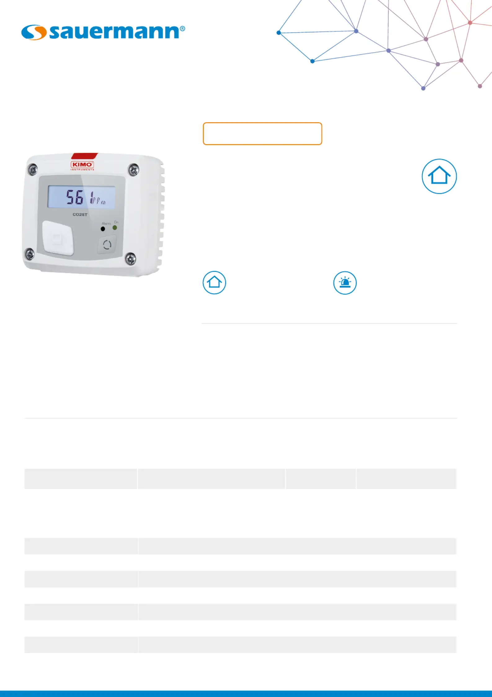
CO2ST-S
CO
2
Stats
CO
2
detector
DATA SHEET
ParameterAccuracyMeasuring rangeResolution*
CO
2
±3% of reading ±50 ppmFrom 0 to 5000 ppm1 ppm
Technical specications
*All the accuracies indicated in this technical datasheet were stated in laboratory conditions, and can be guaranteed for measurements carried out in the same conditions, or carried out with calibration compensation.
Features
• RCR relay output 3A/240 Vac
(NC), power supply 24 Vac/Vdc
• ABS V0 IP20 housing
• “¼ turn” system mounting with
wall-mount plate
• Housing with simplied
mounting system
Visual and audible alarm,
red led in front
Range from 0 to
5000 ppm
Output1 RCR relay. NO (normally opened): 5A / NC (normally closed): 3A / 240 Vac. Common mode voltage <30 Vac
Power supply24 Vac/Vdc ±10%
Consumption3 VA
Relay and alarm statusRed led in front and internal buzzer (70 dB at 10 cm)
Electrical connection2014/30/EU EMC; 2014/35/EU Low Voltage; 2011/65/EU RoHS II; 2012/19/EU WEEE
Raccordement électriqueTerminal block for cables Ø0.05 to 2.5 mm
2
. Carried out according to the code of good practice
PC communicationUSB-mini Din cable
EnvironmentAir and neutral gases
Measured parameter
CO
2
CO
2
Produktspezifikationen
| Marke: | Kimo |
| Kategorie: | Nicht kategorisiert |
| Modell: | CO2ST-S |
Brauchst du Hilfe?
Wenn Sie Hilfe mit Kimo CO2ST-S benötigen, stellen Sie unten eine Frage und andere Benutzer werden Ihnen antworten
Bedienungsanleitung Nicht kategorisiert Kimo

25 September 2025
25 September 2025
24 September 2025
24 September 2025
24 September 2025
24 September 2025
30 August 2025
28 August 2025
28 August 2025
28 August 2025
Bedienungsanleitung Nicht kategorisiert
Neueste Bedienungsanleitung für -Kategorien-
1 April 2026
1 April 2026
1 April 2026
1 April 2026
1 April 2026
1 April 2026
1 April 2026
1 April 2026
1 April 2026
1 April 2026