Kramer SWT3-21-HU-TR Bedienungsanleitung

Kramer Schalter SWT3-21-HU-TR

Lies die bedienungsanleitung für Kramer SWT3-21-HU-TR (4 Seiten) kostenlos online; sie gehört zur Kategorie Schalter. Dieses Handbuch wurde von 4 Personen als hilfreich bewertet und erhielt im Schnitt 4.1 Sterne aus 2.5 Bewertungen. Hast du eine Frage zu Kramer SWT3-21-HU-TR oder möchtest du andere Nutzer dieses Produkts befragen? Stelle eine Frage

Seite 1/4
SWT3 TR- - -21 HU Quick Start
Kramer EMEA
Netherlands
Stroombaan 16
, The Garden 1181VX
Amstelveen
@kramerav.com
Kramer Headquarter:
Kramer Israel
Negev 2 St.
Airport City 7019900
+972 (0)73
- - 265 0200
info_il
@kramerav.com
P/N:
2900- 301831QS
Rev:
2
Scan to go to website
SWT3- - -TR 21 HU Quick Start Guide
This guide helps you install and use your SWT3- -21 HU-TR for the first time.
Go to to download the latest user manual and check if firmware upgrades are link to the user manual
available.
Keep your firmware up- -to date by going to . See the user manual for link to the Resources Tab
firmware download and error recovery information.
Step 1: Check whats in the box
SWT3 TR- - -21 HU 2x1 4K60 HDMI Switcher
Extender
1 Multi signal USB- C cable (1m)
1 Quick start guide
2 Power cords and adapter
Set bracket & 4 Rubber feet
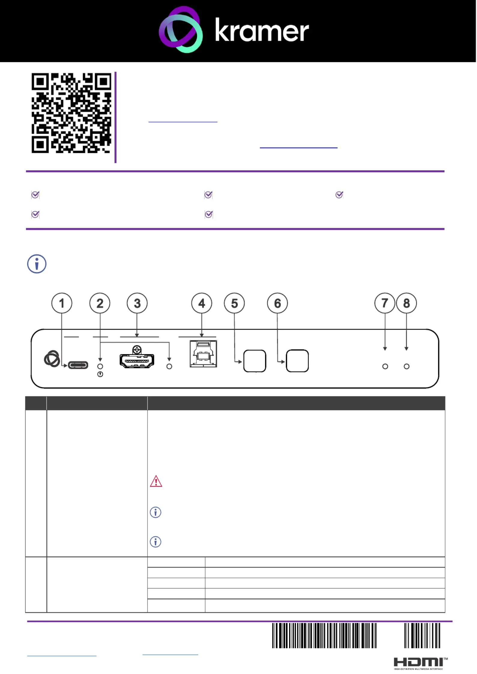
Step 2: -Get to know your SWT3 21- - HU TR
Configuring the device as transmitter (Tx) or receiver (Rx, default) is done via the embedded webpages
settings.
# ction Feature Fun
1
USB-C IN 1 Port
Connect to a USB- LAN): C host (AV + USB +
that supports DisplayPort Alternate Mode, (for example, a share content.laptop) to
to communicate with the USB devices (for example, a PTZ camera) that are
connected to the unit,
to connect to the LAN
to charge the connected sources (that support USB Power Delivery 2.0).s
Make sure to disconnect the USB C cable from your host device before modifying -
the USB type, or before performing a factory reset.
After modifying the USB device type via the web, power cycle the unit after the
webpage indicates that the process is complete.
While charging, the charging icon (to the right of the connector) becomes visible
and lights orange.
2 IN 1 / IN 2 Status LED
(per input port)
LED Status
Indicates
Lights blue
An input is selected and connected with an active AV or AV+USB source.
Flashes blue
An input is selected and has no active AV signal.
Lights magenta
An input is selected and connected with an active USB host only (no AV).
Off
No input is selected.
SWT3- - -21 HU TR
STATUS
NET
SELECT
ON
HDMI IN
HOST
INPUT
DISPLAY
IN IN 1 2
USB-C
# ction Feature Fun
3
IN 2 Ports
HDMI IN
Connect to an HDMI source.
4
HOST USB B
3.2 Connector
Connect to a USB host (for example, a room PC) to communicate with the USB devices (for
example, a PTZ camera) connected on this device.
5
INPUT SELECT Button
Press to select an input. Each press switches to the next input, cycling through all the
available inputs.
1-2 inputs for Tx mode, 1-3 inputs for Rx mode.
6
DISPLAY ON
Button
Press to turn display On/Off.
Button LED lights on after sending Display On message.
Button LED turns off after sending Display Off message.
7
NET LED
LED Status
Indicates
Not lit
No IP address acquired.
Flashes red/yellow
IP mode is set to DHCP, but the unit fails to obtain an IP address
through a DHCP server and is assigned a default IP address.
Lights green
A valid IP address has been acquired.
Flashes green for 60
seconds
A means to identify the device in a system, using the #IDV
command or the webpage FLAG ME button.
8
STATUS LED
LED Status
Indicates
Not lit
No power detected
Lights blue
Power is on and a source is connected.
Lights green
Power is on, and a source and an acceptor are connected.
#
Feature
Function
9 -HDBT RJ 45 Connector Connect to the HDBT RJ-45 connector a paired receiverto (when set to OUT on Tx mode)
or ). transmitter (when set to IN on Rx mode
10
HDMI OUT Connector
Tx Mode: Connect to a local HDMI acceptor (for example, a monitor).
Rx Mode: Connect to an HDMI acceptor.
11
USB 3.2 Port
(1 to 3)
Connect to the USB local devices (for example, a USB camera, a soundbar, microphone
and so on).
12
IR 3.5mm Mini Jack
Connect to an IR emitter or sensor cable for IR extension over HDBT, or IR emitter for IR
signal output per command connected controller (for example, -from LAN ). from KC VB1- /5
13
AUDIO OUT 5-pin Terminal
Block Connector
Connect to a balanced stereo analog audio acceptor.
14 3-I/O pin Terminal Block
(S1 to S2) (GND is common
for I/O and RS-232).
Connect to:
-Input triggering devices (for example, remote buttons or sensors), OR
-Output triggered devices (for example, remote alarm LED indication).
Each of these GPIO ports may be configured as a digital input, digital output, or an analog
input port.
15
RS- -232 3 pin Terminal Block
Connect and control the SWT3-21- - HU TR unit (default), OR
Connect to an RS 232 c- ontrolled device (for example, the connected PTZ USB
camera) to be controlled via a -n IP connected controller (for example, ). KC-VB1/5
16
1G LAN 45 ConnectorRJ-
Connect to LAN.
Make sure to connect only one HDBaseT endpoint (transmitter or receiver) to the
network equipment (switch or router). Connecting both endpoints to the network can cause
network loops and signal issues.
17
20V DC Power Connector
Use the included +20V 6A power supply for powering the unit and charging the source
device connected to the USB-C port.
18
RESET Recessed Button
For restoring factory default settings, press the RESET button and powerconnect to device
(keep pressing longer than 6sec after power connection).
Step 3: -Mount SWT3 21- -HU TR
Install SWT3- - -21 HU TR using one of the following methods:
Mount device with its recommended mounting accessory
to the underside of the table and secure.
Mount the unit in a rack using the recommended rack
adapter
(see
https://www.kramerav.com/SWT3- - -21 HU TR).
Attach the rubber feet and place the unit on a flat surface.
Ensure that the environment (e.g., maximum ambient temperature
& air flow) is compatible for the device.
Avoid uneven mechanical loading.
Appropriate consideration of equipment nameplate ratings should
be used for avoiding overloading of the circuits.
Reliable earthing of rack-mounted equipment should be maintained.
Maximum mounting height for the device is 2 meters.
Step 4: Connect inputs and outputs
Always switch OFF the power on each device before connecting it to your SWT3 TR- - -21 HU .
Connecting the audio output
To a balanced stereo audio
acceptor:
To an unbalanced stereo audio
acceptor:
Step 5: Connect power
Power the device via the LAN or HDBT port. Use the supplied 19V power adapter to power the device and enable the
USB-C port to charge its connected devices.
Safety Instructions (See www.kramerav.com for updated safety information)
Caution:
For products with relay terminals and GPI O ports, please refer to the permitted rating for an external connection, located next to the terminal or in the User Manual.\
There are no operator serviceable parts inside the unit.
Warning
:
Use only the power cord that is supplied with the unit.
Disconnect the power and unplug the unit from the wall before installing.
Transmitter Side Receiver Side
GPIO
ETH USB
USB-C
DP
HDMI
GPIO
ETH
HDBT
USB HDMI
USB USB
RS-232
USB
Power
USBHDMI
IR
SWT3- - -21 HU TR
STATUS
NET
SELECT
ON
HDMI IN
HOST
INPUT
DISPLAY
IN IN 1 2
USB-C
HDMI OUT
IR
AUDIO OUT
RS-232
20V DC
I/O
LAN
HDBT
USB 3.2
RESET
Power
SWT3- - -21 HU TR
STATUS
NET
SELECT
ON
HDMI IN
HOST
INPUT
DISPLAY
IN IN 1 2
USB-C
HDMI OUT
IR
AUDIO OUT
RS-232
20V DC
I/O
LAN
HDBT
USB 3.2
RESET
ETH USB USB
RS-232
HDMI Audio
IR


Produktspezifikationen

Marke: Kramer
Kategorie: Schalter
Modell: SWT3-21-HU-TR

Brauchst du Hilfe?

Wenn Sie Hilfe mit Kramer SWT3-21-HU-TR benötigen, stellen Sie unten eine Frage und andere Benutzer werden Ihnen antworten