Little Giant WF5 Bedienungsanleitung
Little Giant
Pumpe
WF5
Lies die bedienungsanleitung für Little Giant WF5 (8 Seiten) kostenlos online; sie gehört zur Kategorie Pumpe. Dieses Handbuch wurde von 2 Personen als hilfreich bewertet und erhielt im Schnitt 4.5 Sterne aus 1.5 Bewertungen. Hast du eine Frage zu Little Giant WF5 oder möchtest du andere Nutzer dieses Produkts befragen? Stelle eine Frage
Seite 1/8

INTRODUCTION
EN
You are now the owner of the finest fish-safe pond waterfall
designed specifically for garden and koi ponds. Please follow
these instructions to ensure a successful installation. The pond
waterfall is an important element of your water garden pond.
Waterfall features:
• Biovort™ technology for even water distribution on filter pads
and solids separating
• State-of-the-art filter pads
• Industrial corrugated wall design
• Stainless steel band clamp for easy liner attachment
• Back-flush port offers easy maintenance and removal of settling
solid bio-loads, and helps to drain water from the waterfall
• Artificial rock and waterfall ledge with built-in drip ledge
IMPORTANT
Before beginning, read all instructions to familiarize yourself
with the products and additional accessories that can be used.
This will help to ensure that your water garden pond has been
developed to meet your needs and ensure a proper installation.
LOCATING THE WATERFALL
The waterfall can be located adjacent to the pond edge
in a simple configuration. It can also be located many feet
away from the pond with a stream connecting it to the pond. It is
recommended that the waterfall, or waterfall stream entering the
pond, be located on the opposite side of the pond in relation to
the pond skimmer.
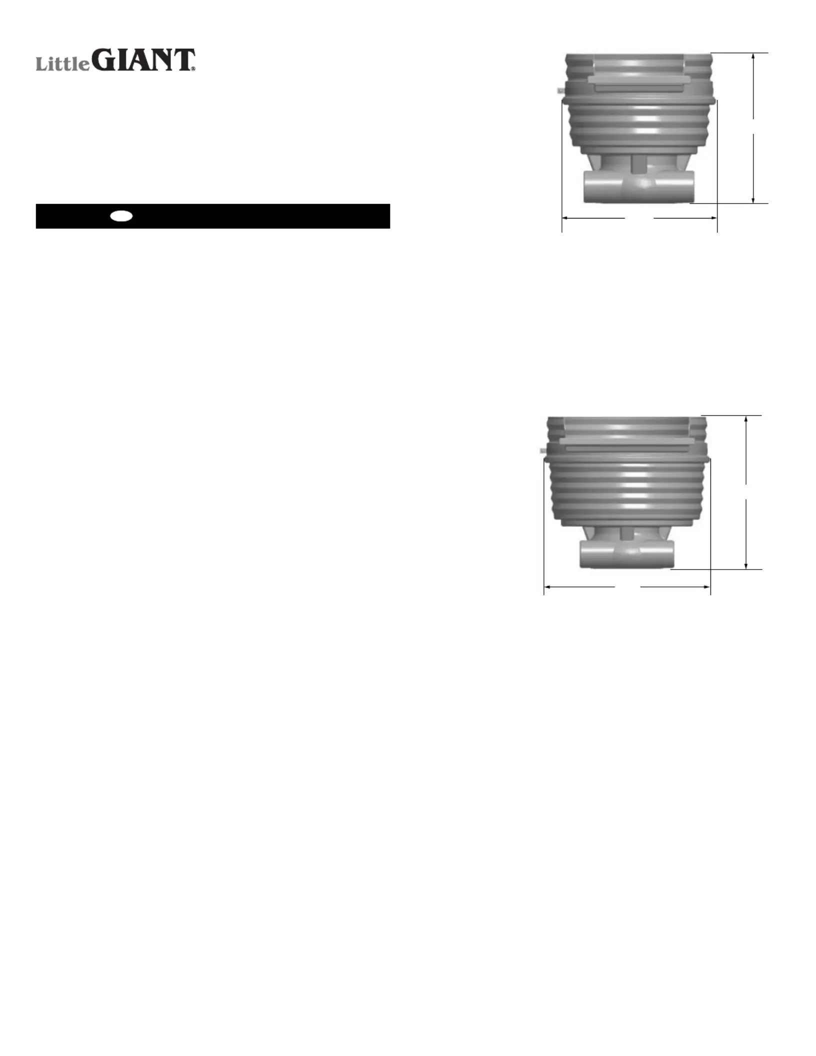
EXCAVATING FOR THE WATERFALL
Refer to Figures 1 and 2 for rough-sizing the hole for the water-
fall vaults. Do not excavate too deep, especially in flat, low-lying
yards. The waterfall is meant to be slightly elevated in relation to
the pond for the most enjoyable water feature presentation.
INSTALLING THE WATERFALL
1. Determine which side of the vault will be the inlet. This is labeled
"INLET" and will always be the right-hand port.
2. If using 2" diameter PVC (rigid or flex), use a 3" hole saw to cut
the inlet opening. If using 3" diameter PVC, use a 4" hole saw.
NOTE: Do not cut the inlet opening with anything other than a
hole saw.
NOTE: The WF5 comes with a 2" adapter, and the WF10 with a
2" and 3" adapter.
3. Install the pipe grommet as shown in Figures 3a, 3b, and 4.
For easier installation, apply the provided Magic Lube to the
inside of the pipe grommet and the outside of the pipe to be
installed.
4. If using a manual back-flush system, it is recommended to cut
the hole in the left-hand port at this time. Refer to the instruc-
tions from the appropriate back-flush kit being used. If using a
Little Giant kit, use a 3" hole saw to cut this opening. The port
is provided with 3" diameter template.
5. Place the empty waterfall vault in the hole or desired location,
and check for clearance around the sides for backfilling.
IMPORTANT: Be sure the bottom of the hole, or surface sup-
porting the bottom of the waterfall vault, is compacted soil.
When excavating the location for the waterfall vault, dig a
round hole and leave ample clearance around for back-filling
with soil. Be sure to leave access to the inlet and back-flush
ports. If a hole is not being excavated, then be sure to back-fill
around the base and heavily compact to support the structure
(see Figure 3a).
IMPORTANT: Set the rear portion of the waterfall approxi-
mately 1/2" higher than the front. This provides the best pre-
sentation of water flowing over the rock, while also minimizing
1
WF5, WF10
Waterfall
Cascade
Caída de agua
31.5”
30.0”
25.0”
26.0”
Figure 1
Figure 2
Model: WF5
Pump Range: 1000 - 5000 GPH
Pond Size: 1000 - 5000 gallons
Material: High density polyethylene
Contents: Waterfall vault, mesh net bag with drawstring and
biological media, 2 filter pads, Biovort
™
, Biovort
™
support plate, artificial rock, band clamp, screw,
washer, and wingnut
Model: WF10
Pump Range: 5000 - 10000 GPH
Pond Size: 5000 - 10000 gallons
Material: High density polyethylene
Contents: Waterfall vault, mesh net bag with drawstring and
biological media, 2 filter pads, Biovort
™
, Biovort
™
support plate, artificial rock, band clamp, screw,
washer, and wingnut
Franklin Electric Co., Inc.
P. O. Box 12010
Oklahoma City, OK 73157-2010
888.956.0000 • Fax: 405.947.8720
www.LittleGiantLandscapeProducts.com
CustomerService-WTS@fele.com

Liner
Toile
Forro
Figure 5
the small amount of water that migrates to the drip ledge
(see Figures 3a and 3b). Back-filling above the level shown
in Figure 3a is optional (see Figure 3b). If desired, additional
soil, rocks, or plants may be incorporated to hide the waterfall
vault.
ATTACHING LINER AND WEIR
By this time the skimmer should be back-filled and the liner can be
attached. Be sure there is an adequate amount of liner available
below the waterfall prior to installing the liner. It is recommended
to have some slack to ensure the liner is not pulled due to rocks
that are added later. There is no need for silicone for the liner
attachment.
1. Hold outstretched liner up against front of waterfall weir ledge.
2. Measure a minimum of 7" out from the weir opening on both sides
of the waterfall and make a mark on the liner (Figure 5).
3. Make a 5" long cut down from the edge of the liner at the
location of the two marks made in Step 2. (Figure 5).
4. Wrap the portion of the liner (in between the two cuts made in
Step 3) over the top of the band clamp.
5. With the liner wrapped around the band clamp, position the
clamp in place on the band clamp sealing ledge (see Figure 6).
Make sure the wrapped portion of the liner doesn’t slip while
being installed.
6. Install the bolt in one end of the band clamp clasp and feed it
through other end of the band clamp clasp. Apply washer and
wing nut. Tighten wing nut until liner is snug (check by pulling
on the liner below the water fall weir ledge).
7. Inspect liner attachment to make sure liner is properly wrapped
around band clamp. This can be checked by raising the liner
up and looking underneath (you should be able to see the
liner protruding down from between the band clamp and the
band clamp sealing ledge on the vault). Tighten wing nut
further, if required. Be careful not to deform the clasp ends of
the band clamp.
INSTALLING THE ARTIFICIAL ROCK
When installing the artificial rock, make sure the surface of the
waterfall weir ledge is clean and dry. Similarly, check the bottom
surface of the artificial rock and make sure it is clean and dry.
Apply a generous amount of a polyurethane foam sealant (which
can be purchased at your local hardware store) to the entire
surface of the waterfall weir ledge. Be sure that some of this foam
is sprayed in the corners as well (Figure 7) so that it is forced
up between the rock and the vertical wall of the weir (Figure 8).
Right port: inlet water supply
Port de droite : entrée
d’alimentation en eau
Puerto derecho: entrada del
suministro de agua
Pipe grommet location
Lieu de la pipe oeillet
Ubicación de la tubería de drenaje timpánico
Left port: back-flush
Port de gauche :
rétrobalayage
Puerto izquierdo:
contraflujo
IMPORTANT:
Back-fill under
vault
IMPORTANT :
Remblayer sous le
bassin
IMPORTANTE:
Relleno
debajo del
bastidor
Install with back
end raised up 1/4”
Installer avec la
partie
arrière surélevée 6
mm (1/4 po)
Instalar con el
extremo posterior
levantado 6 mm
(1/4 pulg)
Figure 3a
Optional back-fill:
soil, rocks
Remblayage facultatif :
terre, rochers
Relleno opcional:
tierra, rocas
Required back-fill
Remblayage exigé
Relleno requerido
Right port: inlet water supply
Port de droite : entrée
d’alimentation en eau
Puerto derecho: entrada del
suministro de agua
Left port: back-flush
Port de gauche :
rétrobalayage
Puerto izquierdo:
contraflujo
Pipe grommet location
Lieu de la pipe oeillet
Ubicación de la tubería de drenaje timpánico
Figure 3b
Inside wall
of vault
Paroi intérieure
de la voûte
Pared interna
de la bastidor
Pipe grommet
Oeillet de tuyau
Tubería anillo protector
Outside wall
of vault
Paroi extérieure
de la voûte
Pared externa
de la bastidor
Figure 4
Figure 6
2

Consult the directions on the sealant for cure times.
If using a natural stone, chisel it to the desired dimensions for the waterfall
weir ledge. The natural stone maximum thickness should be 1-1/2".
COMPONENTS OF THE WATERFALL
BIOVORT
™
SEPARATOR
The waterfall is designed with the Biovort™ technology in mind.
The Biovort™ plays a key part in providing an even dispersion of
water over the filter pads as well as discouraging any larger solids
from reaching the pads. A specially engineered plate is included
to hold the Biovort™ in position.
FILTRATION
The filter is supplied with filter pads to help in catching any debris
that may enter the waterfall vault. A mesh bag with biological
media is also supplied with the waterfall.
WATERFALL MAINTENANCE
If the water flow appears to be less than usual check the pump
inside the skimmer. If the filter media needs cleaning, be careful not
to harm the bacteria. The filter pad can be hit against a sidewalk to
dislodge the debris. Similarly, rinsing the pads or biological media
with pond water will further clean it. Try not to use cold chlorinated
water or the harsh spray from a garden hose to clean the filters.
This will kill bacteria. Also, do not let the filters dry out because it
will kill bacteria.
INTRODUCTION
FR
Vous êtes maintenant propriétaire de la meilleure cascade pour
plan d’eau; sans danger pour les poissons, elle est conçue
spécifiquement pour les jardins et les plans d’eau à koï. Veuillez
suivre ces instructions pour l’installer correctement. La cascade
constitue un élément important de votre plan d’eau de jardin.
Caractéristique de la cascade :
• La technologie Biovort
MC
permet une distribution uniforme de
l’eau sur les disques filtrants et la séparation des solides
• Disques filtrants à la fine pointe de la technologie
• Parois ondulées de catégorie industrielle
• Collier de serrage en acier inoxydable pour faciliter la fixation
de la toile
• Le port de rétrobalayage facilite l’entretien et l’élimination des
charges de solides biologiques de décantage, de même que
l’évacuation de l’eau de la cascade
• Rocher artificiel et rebord de cascade avec rebord intégré
Modèle : WF5
Portée de
la pompe : 3 785 à 18 927 l /h (1 000 à 5 000 gal/h)
Volume du
plan d’eau : 3 785 à 18 927 l (1 000 à 5 000 gal)
Matériau : Polyéthylène haute densité
Contient : Bassin de cascade, sac en mailles de filet avec cordon
et média biologique, 2 disques filtrants, Biovort
MC
,
plaque de support Biovort
MC
, rocher artificiel, collier de
serrage, vis, rondelle et écrou à oreilles
Modèle : WF10
Portée de
la pompe : 18 927 à 37 854 l/h (5 000 à 10 000 gal/h)
Volume du
plan d’eau : 18 927 à 37 854 l (5 000 à 10 000 gal)
Matériau : Polyéthylène haute densité
Contient : Bassin de cascade, sac en mailles de filet avec
cordon et média biologique, 2 disques filtrants,
Biovort
MC
, plaque de support Biovort
MC
, rocher artificiel,
collier de serrage, vis, rondelle et écrou à oreilles
INSTALLATION
IMPORTANT : Avant de commencer, lire toutes les instructions
pour se familiariser avec les produits et les accessoires additionnels
qui peuvent être utilisés. Ceci permet de vous assurer que votre
plan d’eau de jardin a été développé pour répondre à vos besoins
et garantit une installation adéquate.
EMPLACEMENT DE LA CASCADE
La cascade peut-être placée en bordure du plan d’eau, dans une
configuration simple. Elle peut également être placée à quelques
mètres de l’étang avec un ruisseau qui le rejoint. Il est recommandé
de placer la cascade, ou le courant qui entre dans le plan d’eau,
du côté opposé du système d’écumage du plan d’eau.
CREUSAGE POUR LA CASCADE
Consulter les schémas cotés pour évaluer les dimensions du trou
de la cascade (Figures 1 et 2). Prendre soin de ne pas excaver trop
creux, surtout dans les endroits plats et bas. Pour obtenir le meilleur
effet, la cascade doit être un peu plus élevée que le plan d’eau.
INSTALLATION DE LA CASCADE
1. Déterminer de quel côté de la voûte sera située l’entrée.
L’entrée est étiquetée « INLET » et est toujours située sur
l’orifice de droite.
Polyurethane
Foam Sealant
Mousse d’étanchéité en polyuréthane
Sellador de espuma de poliuretano
Figure 7
Foam sealant in corner
(both sides)
Mousse d’étanchéité dans
le coin (des deux côtés)
Sellador de espuma en la esquina (ambos lados)
Figure 8
3
Produktspezifikationen
Marke: | Little Giant |
Kategorie: | Pumpe |
Modell: | WF5 |
Brauchst du Hilfe?
Wenn Sie Hilfe mit Little Giant WF5 benötigen, stellen Sie unten eine Frage und andere Benutzer werden Ihnen antworten
Bedienungsanleitung Pumpe Little Giant
18 August 2025
19 Juli 2025
19 Juli 2025
Bedienungsanleitung Pumpe
- Lezyne
- Batavia
- Gardena
- Eurom
- EUFAB
- Zoeller
- Jabsco
- Milwaukee
- Zehnder Pumpen
- Ultimate Speed
- Generac
- Florabest
- Bestway
- Ebara
- Makita
Neueste Bedienungsanleitung für -Kategorien-
17 August 2025
17 August 2025
17 August 2025
16 August 2025
16 August 2025
16 August 2025
16 August 2025
16 August 2025
16 August 2025
16 August 2025