Mircom MIX-M501MAP Bedienungsanleitung
Mircom Rauchmelder MIX-M501MAP
Lies die bedienungsanleitung für Mircom MIX-M501MAP (10 Seiten) kostenlos online; sie gehört zur Kategorie Rauchmelder. Dieses Handbuch wurde von 22 Personen als hilfreich bewertet und erhielt im Schnitt 4.3 Sterne aus 5 Bewertungen. Hast du eine Frage zu Mircom MIX-M501MAP oder möchtest du andere Nutzer dieses Produkts befragen? Stelle eine Frage
Seite 1/10
MIX-M501MAP Monitor Module
INSTALLATION AND MAINTENANCE INSTRUCTIONS
MC-460-010 1 I56-3316-000
©2008 Mircom
BEfORE INSTALLINg
This information is included as a quick reference installation guide. Refer to
the control panel installation manual for detailed system information. If the
modules will be installed in an existing operational system, inform the opera-
tor and local authority that the system will be temporarily out of service. Dis-
connect power to the control panel before installing the modules.
NOTICE: This manual should be left with the owner/user of this equipment.
gENERAL DESCRIPTION
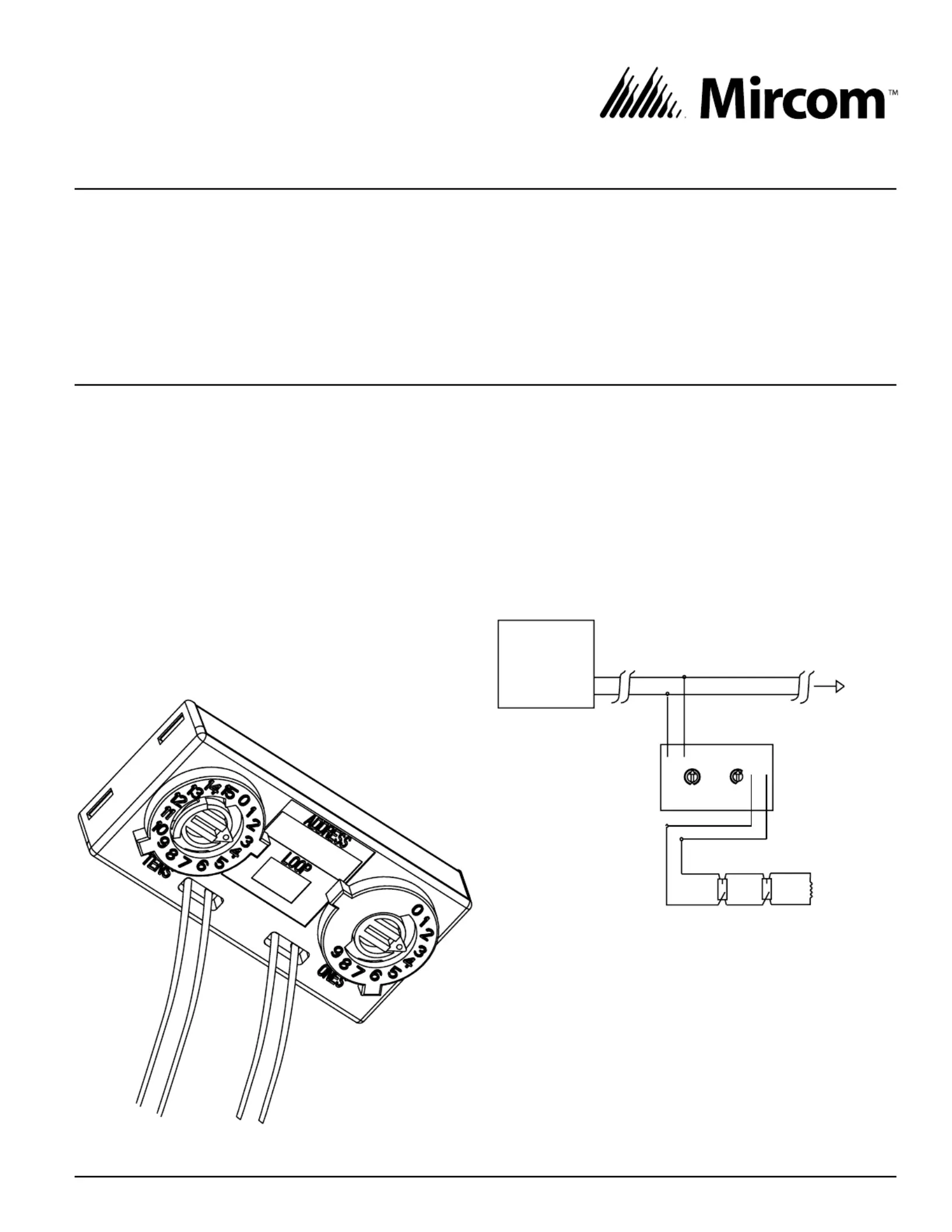
The MIX-M501MAP monitor module can be installed in a single gang junction
box directly behind the monitored unit. Its small size and light weight allow it
to be installed without rigid mounting (see Figure 1). The MIX-M501MAP is
intended for use in intelligent, two-wire systems where the individual address
of each module is selected using rotary decade switches. It provides a two-
wire initiating circuit for normally open contact fire alarm and security devices.
COMPATIBILITy REqUIREMENTS
To ensure proper operation, this module should only be connected to a com-
patible control panel.
fIgURE 1:
C0613-03
MOUNTINg AND WIRINg
NOTE: This module is intended to be wired and mounted without rigid con-
nections inside a standard electrical box. All wiring must conform to appli-
cable local codes, ordinances, and regulations.
1. Connect the red (+) and black ( – ) wires to the positive and negative
loop power leads of the signaling line circuit.
2. Connect the violet (+) and yellow ( – ) wires to a two-wire, normally open
initiating loop.
3. Install the specified EOL resistor value to terminate the initiating loop.
4. Set the address on the module per job drawings.
5. Install the module in the desired mounting location.
fIgURE 2. TyPICAL 2-WIRE STyLE B INITIATINg
CIRCUIT CONfIgURATION:
(+)
(–)
TO
NEXT
DEVICE
BLACK
RED
(+)
(–)
(+)
(–)
VIOLET
YELLOW
0
1
2
3
4
5
6
7
8
9
SIGNAL LINE CIRCUI(SLC)T
47k EOL
INCLUDED
(ELR-47k)
UL LISTED
COMTIBLE PA
CONTROL
PANEL
ALL WIRING
SHOWN IS
SUPERVISED AND
POWER LIMITED
0
7
8
6
5
4
3
2
1
9
10
11
12
13
14
15
C0614-04
SPECIfICATIONS
Nominal Operating Voltage: 15-32 VDC
Maximum Alarm Current: 600 uA
Average Operating Current: 400 µA, 1 communication every 5 seconds, 47k EOL
EOL Resistance: 47K Ohms
Maximum IDC Wiring Resistance: 40 Ohms
Maximum IDC Voltage: 11 Volts
Maximum IDC Current: 400µA
Temperature Range: 32°F to 120°F (0°C to 49°C)
Humidity: 10% to 93% Non-condensing
Dimensions: 1.3˝ H × 2.75˝ W × 0.65˝ D
Wire Length: 6˝ minimum
25 Interchange Way, Vaughan Ontario, L4K 5W3
Phone: 905.660.4655; Fax: 905.660.4113
Produktspezifikationen
| Marke: | Mircom |
| Kategorie: | Rauchmelder |
| Modell: | MIX-M501MAP |
Brauchst du Hilfe?
Wenn Sie Hilfe mit Mircom MIX-M501MAP benötigen, stellen Sie unten eine Frage und andere Benutzer werden Ihnen antworten
Bedienungsanleitung Rauchmelder Mircom

10 Oktober 2025
18 August 2024
Bedienungsanleitung Rauchmelder
Neueste Bedienungsanleitung für -Kategorien-
12 Januar 2026
10 Januar 2026
6 Januar 2026
30 Dezember 2026
29 Dezember 2026
10 Dezember 2025
9 Dezember 2025
8 Dezember 2025
12 November 2025
5 November 2025