NEO Tools 71-200 Bedienungsanleitung
NEO Tools
Laser-Nivelliergerät
71-200
Lies die bedienungsanleitung für NEO Tools 71-200 (15 Seiten) kostenlos online; sie gehört zur Kategorie Laser-Nivelliergerät. Dieses Handbuch wurde von 3 Personen als hilfreich bewertet und erhielt im Schnitt 4.7 Sterne aus 2 Bewertungen. Hast du eine Frage zu NEO Tools 71-200 oder möchtest du andere Nutzer dieses Produkts befragen? Stelle eine Frage
Seite 1/15

Poziomnica laserowa
Oryginalna instrukcja obsługi
71 200-
UWAGA! PRZED PRZYSTĄPIENIEM DO UŻYTKOWANIA SPRZĘTU
NALEŻY UWAŻNIE PRZECZYTAĆ NINIEJSZĄ INSTRUKCJĘ I
ZACHOWAĆ JĄ DO DALSZEGO WYKORZYSTANIA.
INFORMACJE DOTYCZĄCE BEZPIECZEŃSTWA
• Nie wolno wprowadzać żadnych modyfikacji w urządzeniu.
• Urządzenie laserowe należy użytkować zgodnie z zaleceniami
producenta.
• Zaleca się przeprowadzenie kontroli dokładności przed pierwszym
użyciem oraz okresowych kontroli w trakcie okresu użytkowania
urządzenia.
• Nie wolno kierować wiązki światła laserowego ku oczom
osób postronnych i zwierząt. Promieniowanie lasera może
uszkodzić narząd wzroku.
• Zawsze należy się upewnić czy światło lasera nie jest skierowane
na powierzchnie odbijające. Powierzchnia odbijająca wiązkę
lasera mogłaby odbić taką wiązkę w kierunku operatora, lub osób
trzecich.
• Nie należy pozwalać dzieciom na obsługę tego urządzenia.
Nie dopuszczać dzieci do miejsca pracy podczas ustawień i
w czasie używania urządzenia.
• Nie przechowuj lasera w miejscu narażonym na bezpośrednie
padanie promieni słonecznych lub w miejscu o wysokiej
temperaturze. Obudowa i niektóre elementy zbudowane są z
tworzywa sztucznego, a działanie temperatury może powodować
degradację materiału.
• Nieużywany sprzęt przechowywać w suchym miejscu,
niedostępnym dla dzieci.
• W przypadku przechowywania przez dłuższy czas, wyjmij
akumulator, aby zapobiec możliwym uszkodzeniom.
• Nie wolno wymieniać zespołu laserowego na urządzenie innego
typu. Wszelkie naprawy powinny być wykonane przez serwis
producenta.
• Urządzenie zostało wyposażone w laser klasy 2 zgodny z EN
60825 1:2014.-
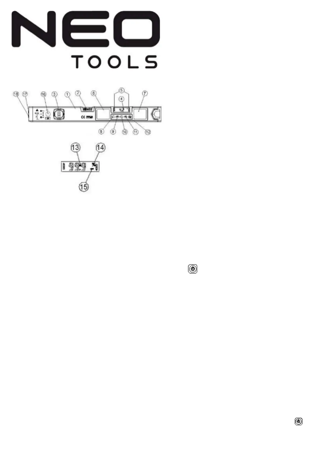
Przeznaczenie: Poziomica laserowa składa się z trzech komponentów:
tradycyjnej poziomicy z libellą, komponentu do pomiarów cyfrowych oraz
komponentu laserowego (patrz rysunek 1). Libella może być użyta w celu
określenia pionu i poziomu, wyświetlacz LCD umożliwia pomiar i odczyt
dowolnego kąta, podczas gdy wiązka lasera umożliwia wyświetlenie
punktu odniesienia, linii poziomu lub prostopadłych do siebie
skrzyżowanych linii pionu i poziomu.
Specyfikacja:
• Długość fali: 635nm- 670nm
• Moc optyczna: ≤1mw;
• Klasa lasera: 2;
• Dokładność systemu laserowego: ±3mm/10m
• Zakres pomiaru cyfrowego °(4 X 90°): 0°~360
• Dokładność pomiaru kąta dla: 0°i 90°±0.1°
• Dokładność pomiaru kąta dla 89: 1°÷ °±0.2°
• Dokładność pomiaru libellą dla położenia poziomego :
0.029°=0.50mm/m
• Dokładność pomiaru libellą dla położenia pionowego :
0.043°=0.75mm/m
• 3Zasilanie: V (baterie alkaliczne AAA 1.5V)
• Temperatura otoczenia w czasie pracy: 0°C ~+40°C
• Temperatura przechowywania: - 10°C~+60°C
• Sygnał dźwiękowy dla kątów: 0° ,45°,90°
Wymiana baterii:
• Otwórz pokrywkę gniazda baterii;
• Włóż 2 baterie AAA 1.5V upewniając się, że są wkładane odpowiednią
stroną;
• Zamknij pokrywkę gniazda baterii;
Instrukcja użytkowania:
1.Włączanie / Wyłączanie
:
:
:
::
Naciśnij przycisk oznaczony ON/OFF w
przedniej części poziomicy.
2. Laserowy punkt odniesienia: Przesuń przełącznik na końcu
poziomicy w pozycję środkową. Wówczas ustawiony zostanie tryb pracy
znacznika laserowego. Aby ustawić kierunek wiązki lasera poziomo,
należy skorzystać z libelli lub odczytać kąt 0° z wyświetlacza cyfrowego.
Po ustawieniu poziomicy wiązka lasera wskazywać będzie poziom.
• Laserowa linia poziomu: Przesunięcie aparatury w pozycję dolną
(górna soczewka na wylocie wiązki lasera) spowoduje przejście w tryb
lasera liniowego. Wówczas poprawnie ustawiona poziomica
wyświetlać będzie linię poziomą.
• Linie pionu i poziomu: Przesunięcie aparatury w pozycję górną (dolna
soczewka na wylocie wiązki lasera). Spowoduje rozdzielenie wiązki na
2 prostopadłe linie krzyżujące się pod kątem prostym, wskazujące
płaszczyzny pionową i poziomą.
3. Pomiar cyfrowy
Funkcje przycisków (patrz rysunek 1.)
1. : Włączenie / wyłączenie wyświetlacza LCD
2. HOLD: Zamrożenie pomiaru
3. ABS/CAL: Zmiana trybu / kalibracja
4. LIGHT: Podświetlenie ekranu LCD
5. °
%
%
%
%%
: Zmiana jednostki pomiaru
Instrukcje pomiaru
1. Włączanie / wyłączanie : Naciśnij przycisk włączenia / wyłączenia aby
włączyć wyświetlacz LCD. Naciśnij ponownie by wyłączyć. Urządzenie
wyłączy się automatycznie po około 5 minutach bez naciśnięcia
przycisku. W przypadku przytrzymania przycisku przez 8 sekund
urządzenie wyłącza się, a ustawienia zostają usunięte. Wówczas po
ponownym naciśnięciu przycisku i włączeniu urządzenia, wyświetlony
zostanie komunikat „CAL1” i poziomica przejdzie w tryb kalibracji (patrz
kolejny rozdział).
2. Kalibracja poziomu: Przy pierwszym uruchomieniu, lub po
przytrzymaniu włącznika przez 8 i ponownym włączeniu, wyświetlony
zostanie komunikat „CAL1”. Wówczas należy dokonać kalibracji
stosując następujące kroki:
a. Ustaw poziomicę w poziomie lub pionie (patrz rysunek 2) na płaskiej i
gładkiej powierzchni. Wyceluj w wyznaczone miejsce, po czym naciśnij
przycisk ABS/CAL. Napis zacznie mrugać, sygnalizując „ ”CAL1
trwający zapis informacji. Po kilku sekundach mruganie ustąpi.
Wyświetlony zostanie komunikat „CAL2”.
b. Nie zmieniając położenia poziomicy, obróć ją o 180°, po czym naciśnij
przycisk ABS/CAL. Napis „CAL2” zacznie mrugać, sygnalizując
trwający zapis informacji. Po kilku sekundach mruganie ustąpi
sygnalizując koniec zapisu informacji. Jeżeli w trakcie trwania procesu
chcesz opuścić tryb kalibracji, przytrzymaj przycisk przez 4
sekundy.
3. Pomiar kąta bezwzględnego : Domyślny tryb pracy urządzenia, w
którym kąt mierzony jest względem poziomu (kąta 0°). O jego
aktywności informuje komunikat wyświetlany w prawej części „ ”ABS
wyświetlacza LCD.

4. Pomiar kąta względnego: Aby zmierzyć kąt względem powierzchni
nachylonej, naciśnij przycisk ABS/CAL w celu przejścia w tryb pomiaru
kąta względnego. Komunikat „ABS” zniknie, a wyświetlany kąt przyjmie
wartość 0°. Od teraz pomiar będzie odbywał się względem ustalonej
pozycji. Ponowne naciśnięcie przycisku (lub ponowne ABS/CAL
uruchomienie urządzenia) spowoduje powrót w tryb pomiaru
bezwzględnego względem poziomu.
Pozostałe funkcje:
1. Wybór jednostki pomiarowej: Naciśnij przycisk %, w celu zmiany
jednostki pomiarowej ze stopni na procenty (nachylenie) (kąt) .
2. Zamrożenie pomiaru: Naciśnij przycisk HOLD w celu zamrożenia
pomiaru. Naciśnij przycisk ponownie, aby wyłączyć funkcję.
3. Wskaźniki położenia : Po obu bokach ekranu LCD wyświetlone
zostaną strzałki wskazujące kierunek w stronę kątów 0° lub 90° Strzałka
zniknie po osiągnięciu pionu lub poziomu.
4. Sygnał dźwiękowy: Osiągnięcie kąta 0°, 45° lub 90° przez poziomicę
będzie sygnalizowane poprzez wydanie dźwięku.
5. Odwrócenie wyświetlacza : W celu wygodnego odczytu, gdy
poziomica zostanie odwrócona do góry spodem, obróceniu ulegnie
również obraz na wyświetlaczu LCD.
6. Podświetlenie ekranu LCD : Naciśnij przycisk light w celu
podświetlenia ekranu LCD, co ułatwi pracę w zaciemnionych miejscach.
7. Wskaźnik niskiego poziomu baterii : Zostanie wyświetlony w
przypadku niskiego poziomu baterii. Wówczas zalecana jest ich
wymiana.
Rysunek 1:
1.korpus poziomicy
2.libella pozioma
3.libella pionowa
4.wartość pomiaru wyświetlana cyfrowo
5.Wskaźniki położenia względem 0° lub 90°
6.korpus wyświetlacza
7.gniazdo baterii
8.zmiana jednostki pomiaru (kąt / nachylenie)
9.włącznik podświetlenia ekranu LCD
10.zmiana trybu / przycisk kalibracji
11.przycisk zamrożenia pomiaru
12.włącznik wyświetlacza
13.wskaźnik niskiego poziomu baterii.
14.wskaźnik jednostki pomiarowej
15 wskaźnik trybu pomiaru.
16.włącznik lasera
17.soczewka krzyżowa
18.soczewka liniowa
Kalibracja poziomnicy elektronicznej
Podczas pierwszego uruchomienia konieczna będzie kalibracja
poziomnicy elektronicznej. Zamiast kąta na wyświetlacz LCD będzie a
widoczne wskazanie „CAL1”. Należy poziomnicę przyłożyć dolna
powierzchnią pomiarową do płaskiej powierzchni poziomej lub pionowej.
Zaleca się to zrobić w rogu np. ścian, żeby możliwie najdokładniej udało się
poziomnicę odwrócić. Nacisnąć przycisk „ABS/CAL”, wskazanie „CAL1”
zacznie pulsować, kiedy prze-stanie zmieni się na wskazanie „CAL2”, należy
wtedy obrócić poziomnicę o 180 stopni i przyłożyć ją w to samo miejsce co
poprzednio, ale górną powierzchnią pomiarową. Ponownie nacisnąć przycisk
„ABS/CAL”, wskazanie „CAL2” zacznie pulsować, kiedy przestanie, zmieni
się automatycznie na wskazanie kąta, a kalibracja będzie ukończona.
Jeżeli zajdzie potrzeba kalibracji poziomnicy w trakcie pracy, należy przy
włączonej poziomnicy nacisnąć i przytrzymać przez okres ok. 8 sekund
przycisk „ABS/CAL”. Następnie postępować jak opisano powyżej. Uwaga!
Nie należy dokonywać kalibracji na zbyt nachylonych powierzchniach, jeżeli
wskazanie „CAT1” lub „CAT2” nie przestaje pulsować, oznacza to zbyt
nachyloną powierzchnię. Przy wyborze powierzchni należy się kierować
wskazaniem jednej z libelli spirytusowych.
Informacje dla bezpieczeństwa:
1. Jeżeli nie zamierzasz używać urządzenia przez co najmniej 3 miesiące,
wyjmij baterie w celu zapobiegania ich wyciekaniu. Baterie powinny być
przechowywane w suchym i chłodnym miejscu.
2. W przypadku wycieku z baterii należy usunąć płyn miękką ścierką
unikając kontaktu ze skórą.
3. W trosce o środowisko zużyte baterie należy umieścić w wyznaczonym
do tego miejscu. Baterii nie należy mieszać z innymi odpadami ani spalać.
4. Pod żadnym pozorem nie należy umieszczać poziomicy w wodzie.
Uwaga:
• Nigdy nie patrz bezpośrednio na wiązkę lasera, gdyż grozi to
uszkodzeniem wzroku;
• Nie patrz na wiązkę lasera za pośrednictwem przyrządów optycznych;
• aTrzym j narzędzie oraz wiązkę lasera z dala od dzieci ;
Produktów zasilanych elektrycznie nie należy wyrzucać
wraz z domowymi odpadkami, lecz oddać je do utylizacji
w odpowiednich zakładach. Informacji na temat utylizacji
udzieli sprzedawca produktu lub miejscowe władze.
Zużyty sprzęt elektryczny i elektroniczny zawiera
substancje nieobojętne dla środowiska naturalnego.
Sprzęt nie poddany recyclingowi stanowi potencjalne
zagrożenie dla środowiska i zdrowia ludzi.
GWARANCJA I SERWIS
Warunki gwarancji oraz opis postępowania w przypadku reklamacji
zawarte są w załączonej Karcie Gwarancyjnej.
Serwis Centralny GTX Service Sp. z o.o. Sp.k.
ul. Pograniczna 2/4 tel. +48 22 364 53 50
02 285 Warszawa- e-mail bok@gtxservice.com
Sieć Punktów Serwisowych do napraw gwarancyjnych i pogwarancyjnych
dostępna na platformie internetowej gtxservice.pl
Zeskanuj QR kod i wejdź na gtxservice.pl
EN
Laser Level
Original User Manual
71 200-
CAUTION! BEFORE OPERATING THE DEVICE, READ THIS USER
MANUAL CAREFULLY AND KEEP IT FOR REFERENCE.
SAFETY INFORMATION
• Do not attempt to modify this device.
• Use this laser device strictly in compliance with manufacturer’s
guidance.
• It is recommended to test the accuracy before the first use and retest it
periodically during operation.
• Do not direct the laser into the eyes of anyone or any animals/pets.
Laser radiation can damage the eyes.
• Always make sure that the laser beam is not directed at any reflective
surface. A reflective surface can reflect the laser beam back into the
eyes of the operator or a bystander.
• Do not allow children to operate this device. Never allow children
to access the device’s site of operation during adjustment or use.
• Do not store the laser device in direct exposure to sunlight or near
sources of high heat. The body and some components of the device are
plastic, which can be damaged by high temperature.
• If unused, keep the device in a dry place away from children.
• Do not replace the laser beam system with any other type of laser
device. Always have the device repaired by the authorized service of
the manufacturer.
• -This device features a class 2 laser in compliance with EN 60825
1:2014.
Intended use:
Laser Level consists of 3 parts: traditional bubble measuring equipment,
new measuring equipment with digital angle display and laser measuring
equipment. (See specification Figure 1.); bubble measuring equipment can
be used for measuring and correcting the product’s horizontal and vertical
alignment, measuring equipment of digital display the angle can be used
to measure and check any angle conditions of the product; laser auto -
setting level measuring equipment can provide the reference laser point,
reference line of laser level, reference laser crossing lines.
Technical data:
• Laser wavelength: 635nm-670nm
• Luminous power: ≤1mw;
• Radiation class: 2;
• Radiation point accuracy: ±3mm/10m
• The range of digital angle measurement °(4 X 90°): 0°~360
• The accuracy of angle measuring: 0 90°and °±0.1°
• The accuracy of angle measuring: 1 89° to °±0.2°

• The accuracy of bubble measuring:0.029° = 0.50mm/m basis on the
underside
• The accuracy of bubble measuring: 0.043°=0.75mm/m top of the
position
• Batteries: 3V (AAA 1.5V alkaline batteries )
• Operating ambient temperature: 0°C ~+40°C
• Storage temperature: 10°C~+60°C-
• Sound reminder of specific angle 0° ,45°,90°
Battery assembling:
• Open the battery box cover;
• Put two batteries (AAA 1.5V alkaline battery) into the box with
anode outward;
• Close the box cover
Operation instruction of:
1.Put on / put down
:
:
:
::
press the button switch marked on/off at the head
of the rule, put the radiation’s switch on;
2.Radiation point Reference: Move the laser converter at the end of the
device into the center position. Laser will generate reference point (dot).
To align laser horizontally use the level bubble or read the 0° angle from
digital display. Laser dot will be reference point of level.
• Level reference laser beam: As soon as the laser converter is
pushed down to the the lower position (laser will go through an upper
lens) a horizontal reference laser beam will be produced from the laser
generator.
• Cross-shaped reference laser beam: As soon as the laser
converter is pushed up to the upper position (laser will go through an lower
lens) shaped reference laser beam will be produced from the laser Cross-
generator (one horizontal line and one vertical line).
3. Digital angle measuring
Button functions (see figure 1)
1. : Power (LCD) on/off button
2. HOLD: Measure freeze
3. ABS/CAL: mode switch / adjust button
4. LIGHT: LCD backlight on/off button
5. °
%
%
%
%%
: Unit switch (angle/slope)
Operation Instruction
1. Turning On/Off: Press on/off button to turn LCD display on. Press
the button again to turn it off. After approximately 5 minutes without
pressing any button, digital display will turn off automatically.
Pressing the button for more than 8 seconds will cause device to turn
off and delete saved data. Then short press the button again. “CAL1”
sign will show on the screen. Device is now in adjusting (calibration)
mode and must undergo adjustment of level position to work properly
(see level zero adjusting below).
2. Level zero position adjusting: When the user uses equipment for
the first time or push the on/off button more than 8 seconds when
turning off, LCD will show the sign “CAL1”. Then the following steps
must be done to adjust level zero position.
a. Put the level upon a horizontal plane (or vertical plane), (see figure
2). Aim at the designated location or sign, short press the
“ABS/CAL“, then the CAL2 sing will start flashing on the LCD (It
means the first data collection is going on). After few seconds CAL1
sign will stop flashing. CAL2 sign will appear on LCD screen.
b. Rotate the level by 180° without changing it’s position. Press
ABS/CAL button. CAL2 sign will start flashing on LCD (It means the
second data collection is going on). After a few seconds CAL2 sign
will stop flashing, which means data collection is completed. During
adjustment process you can press for 4 second to exit
calibration mode.
3. Measurement of absolute angle: Default mode in which angle is
measured in relation to 0° level position. This mode is indicated by
“ABS” sign on the right side of LCD screen.
4. :The measurement of relative angle To measure angle in relation
to inclined surface, press button to enter relative angle ABS/CAL
measurement mode. ABS sign on the right side will disappear, and
displayed angle will change to 0°. Angle will be now measured in
relation to new 0° angle. Press the button again (or restart ABS/CAL
the device) to exit relative measurement, and enter absolute angle
measurement mode.
Other functions:
1. Degree/slope rate conversion function: Press %, to change unit of
measurement from degrees (angle) to percentage (slope).
2. Function of measurement freeze: Press HOLD to freeze the digital
measurement. Press the button again to exit function.
3. Angle value indicator: An arrow indicator can be found on both ends
of the LCD, so it’s easier to adjust the angle value. Just adjust the
horizontal ruler (scale) in the direction indicated by the arrow until the
arrow disappeared when it reaches 0 or 90 degrees.
4. Sound indicator: -Whenever the laser level digital actual value
horizontal ruler (scale) measures 0, 45. or 90 degrees, there will be two
sound of indicator
5. LCD inversion displaying function: When digital level is rotated
upside down, the LCD screen will display inversely in order to give a -
convenient look of the result.
6. LCD luminous function: press light, to turn on backlight of LCD so it’s
easier to use the device in dark places.
7.low-battery indicator: if the voltage of the battery is too low, a battery
sign will show up on the screen to remind you to change the battery.
Figure 1:
1.ruler body
2.vertical bubble
3.horizontal bubble
4.digital shown angle value
5.indicators of angle value adjusting
6.angle display
7.battery box
8.conversion button of degree/angle slope rate
9.LCD backlight on/off button
10.switch mode/adjusting button
11.measure value freeze button
12.LCD screen on/off button
13.low voltage indicator
14.degree / angle slope rate display
15.absolute angle / relative angle display
16.laser switch
17.cross shaped prismatic mirror-
18.line shaped prismatic mirror-
Calibration of the electronic level
For the first start the calibration of the electronic level will be necessary.
Instead of an angle, on the LCD there will be visible indicating “CAL1”. You
should place the lower measuring surface to a flat, horizontal or vertical,
surface It is recommended that you do this in the corner, for example of
walls, in order to turn the level as accurately as possible. Push the button
„ABS/CAL”, the indication “CAL1” will flash, when it stops, the indication will
change to „CAL2”, at that moment you should rotate the level by 180
degrees and place it in the same place as before, but by its upper measuring
surface. Press the button „CAL2” again, the indication „CAL2” will flash,
when it stops, the angle indication will change automatically to the indication
of the angle, and calibration will be completed. If you need to calibrate the
level in the course of work, you should, when the lever is on, press the
button’ ABS/CAL “ and hold it for a period of approx. 8 seconds. Then
proceed as it has been described above. Attention! Calibration should not
be performed on too inclined surfaces, if the indication “CAT1” or “CAT2”
does not stop flashing, it means that the surface is too inclined. When
choosing the surface you should be guided an indication of one of the spirit
level.
Designation of safety
1.If you are not going to use the battery, for at least 3 months, please take
it out to prevent leaking, the battery should kept in the cool and dry place;
2. If the battery is leaked, please clean the liquid with soft cloth and avoid
contact with skin;
3. In order to protect polluting the environment please put the scrap
batteries into recycle box. It’s forbidden reject and burn them;-
4.Don’t put the level into the water absolutely.
Warning:
• Don’t look into the laser beam with eyes directly, to avoid serious injury;
• Don’t look into the laser beam with optical apparatus directly;
• Don‘t let child touch or close to the laser beam;
Do not dispose of electrically powered products with
household wastes, they should be utilized in proper
plants. Obtain information on wastes utilization from
your seller or local authorities. Used up electric and
electronic equipment contains substances active in
natural environment. Unrecycled equipment
constitutes a potential risk for environment and
human health.
Produktspezifikationen
Marke: | NEO Tools |
Kategorie: | Laser-Nivelliergerät |
Modell: | 71-200 |
Brauchst du Hilfe?
Wenn Sie Hilfe mit NEO Tools 71-200 benötigen, stellen Sie unten eine Frage und andere Benutzer werden Ihnen antworten
Bedienungsanleitung Laser-Nivelliergerät NEO Tools
21 Juli 2025
20 Juli 2025
20 Juli 2025
20 Juli 2025
20 Juli 2025
20 Juli 2025
14 Juli 2025
Bedienungsanleitung Laser-Nivelliergerät
- Trotec
- Steinberg
- Craftsman
- Alpha Tools
- Skil
- Ermenrich
- PLS
- Makita
- Neo
- DeWalt
- Dedra
- Laserliner
- Klein Tools
- Proline
- Milwaukee
Neueste Bedienungsanleitung für -Kategorien-
19 Juli 2025
19 Juli 2025
18 Juli 2025
17 Juli 2025
16 Juli 2025
16 Juli 2025
16 Juli 2025
16 Juli 2025
16 Juli 2025
15 Juli 2025