PAC RP3-GM11 Bedienungsanleitung
PAC Nicht kategorisiert RP3-GM11
Lies die bedienungsanleitung für PAC RP3-GM11 (2 Seiten) kostenlos online; sie gehört zur Kategorie Nicht kategorisiert. Dieses Handbuch wurde von 28 Personen als hilfreich bewertet und erhielt im Schnitt 4.9 Sterne aus 2 Bewertungen. Hast du eine Frage zu PAC RP3-GM11 oder möchtest du andere Nutzer dieses Produkts befragen? Stelle eine Frage
Seite 1/2
RP3-GM11
Radio Replacement Interface for General Motors Vehicles
Pacifi c Accessory Corporation
®
| Santa Ana, California 92705 | Ph. 866-931-8021 | [email protected]
©2013 Pacifi c Accessory Corporation
www.pac-audio.com
Rev. 120513
3
3
Introduction & Features
Important Notes
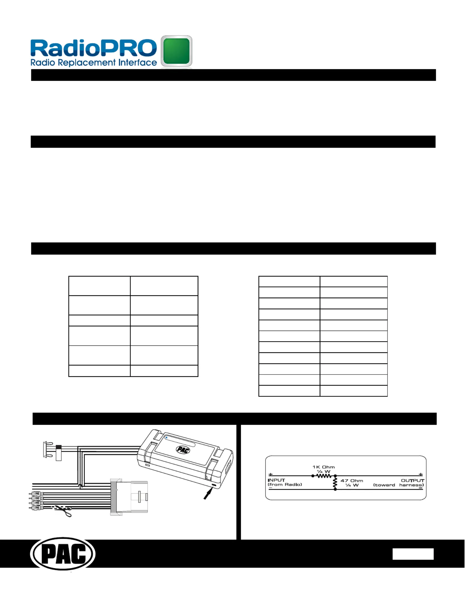
Wiring Connection Chart
Illustration / Schematic
The RP3-GM11 interface allows the replacement of a factory radio in select General Motors vehicles with Class II radios. Using
this interface will retain factory features such as Warning Chimes and BOSE® amplifi er (Standard or Premium) when the original
radio is removed. The RP3-GM11 provides data bus driven outputs such as retained accessory power (RAP), vehicle speed
sensor (VSS), illumination, reverse trigger and parking brake. The RP3-GM11 also provides a secondary output for adding an
optional PAC Steering Wheel Control (SWC) retention interface (SWI-RC, SWI-PS, SWI-JACK, SWI-ECL2 or SWI-X). Rear Seat
Controls (RSC) if equipped will also be retained with the SWI interface.
1. When used in Non-BOSE® applications simply cut off the RCA connectors and connect the remaining wires to the aftermarket
radios high level speaker outputs.
2. For BOSE® systems, the recommended line level input is between 2-4 volts from the aftermarket radio.
3. RSC buttons that are identical to the SWC will mimic the SWC one for one
4. To prevent over driven audio when installing the interface into a vehicle with a BOSE® system, and the aftermarket radio does
not have low level outputs, then an LOC (part # SOEM-4 or LP3-4) is recommended to match the input voltage or you can create
an audio attenuation circuit (see diagram 2 below for audio attenuation wiring).
5. Use the 4 position selector switch located on the side of the interface to select the best chime output volume for your specifi c
installation .
Red / WhiteParking Brake
Output (-)*
Purple / WhiteVehicle Speed
Output*
Blue / WhiteAmp Turn On Input
RedAccessory Output
(10 amp)
Orange / WhiteIllumination Output
(+)*
GreenReverse Output (+)*
Interface Connector
YellowBattery +12v
BlackGround
BlueAntenna On Input
WhiteFront L + input
White / BlackFront L - input
GreyFront R + input
Grey / BlackFront R - input
GreenRear L + input
Green / BlackRear L - input
PurpleRear R + input
Purple / BlackRear R - input
Vehicle Connector
Audio Attenuation Circuit for RP3-GM11
One channel shown
*Not all radios will have these
connections. Please insulate
these wires when not used.
Diagram 1
Chime Volume Adjustment
Cut for Non-Bose systems
Aftermarket Radio
Connections
To Vehicle
Connector
Connect to SWC
Interface. Program
for Version 2.
To optional SWC interface
Acc On
LED
Produktspezifikationen
| Marke: | PAC |
| Kategorie: | Nicht kategorisiert |
| Modell: | RP3-GM11 |
Brauchst du Hilfe?
Wenn Sie Hilfe mit PAC RP3-GM11 benötigen, stellen Sie unten eine Frage und andere Benutzer werden Ihnen antworten
Bedienungsanleitung Nicht kategorisiert PAC

10 August 2025
9 August 2025
9 August 2025
9 August 2025
9 August 2025
11 Juli 2025
11 Juli 2025
11 Juli 2025
10 Juli 2025
10 Juli 2025
Bedienungsanleitung Nicht kategorisiert
Neueste Bedienungsanleitung für -Kategorien-
3 April 2026
3 April 2026
3 April 2026
3 April 2026
3 April 2026
3 April 2026
3 April 2026
3 April 2026
3 April 2026
3 April 2026