Salus PMV21 Bedienungsanleitung
Salus Nicht kategorisiert PMV21
Lies die bedienungsanleitung für Salus PMV21 (2 Seiten) kostenlos online; sie gehört zur Kategorie Nicht kategorisiert. Dieses Handbuch wurde von 22 Personen als hilfreich bewertet und erhielt im Schnitt 4.6 Sterne aus 7 Bewertungen. Hast du eine Frage zu Salus PMV21 oder möchtest du andere Nutzer dieses Produkts befragen? Stelle eine Frage
Seite 1/2
PRODUCT COMPLIANCE
This product complies with the essential requirements of the following EC Directives:
•Electro-Magnetic Compatibility Directive 2014/30/EU
•Low Voltage Directive 2014/35/EU
•RoHS 2011/65/EU
SAFETY INFORMATION
These instructions are applicable to the SALUS Controls model stated on the front cover of this
manual only, and must not be used with any other make or model.
This accessory must be fitted by a Competent person, and installation must comply with the
guidance provided in the current editions of BS7671 (IEE Wiring Regulations) and Part ‘P’ of the
Building Regulations. Failure to comply with the requirements of these publications could lead
to prosecution.
Always isolate the AC Mains supply before removing or refitting the actuator assembly.
Please leave these instructions with the end user where they should be kept in a safe place for
future reference.
INTRODUCTION
A motorised valve is used to control the flow of water in a central heating system. The motorised
valve can be used for control of both heating and hot water, and it works by controlling the flow
of water from the heating boiler to other parts of the system.
There are two types of motorised valve used in domestic heating systems: two port (also called
zone valves), and three port (also called mid position valves). SALUS Controls offers both types
of valve in a range of standard port sizes.
FEATURES
•Two port option in 1”, 22mm, 3/4” and 28mm sizes
•Removable actuator assembly
•Manual lever and position indicator
•Spring return
•Industry standard wiring
INSTALLATION
Please read the important safety information at the start of this manual before you begin to
install the device.
Before Installation
This valve must only be installed in compatible systems. Before installing, please check that:
•The system pipework has been flushed out to remove any residue.
•There is enough clearance around the valve to allow removal and refitting of the actuator.
•The valve is not installed with the actuator facing down.
•The supply voltage is the same as the voltage indicated on the actuator cover.
•The mains water pressure and the pressure differentials between valve ports are suitable for
this valve (see Product Specification).
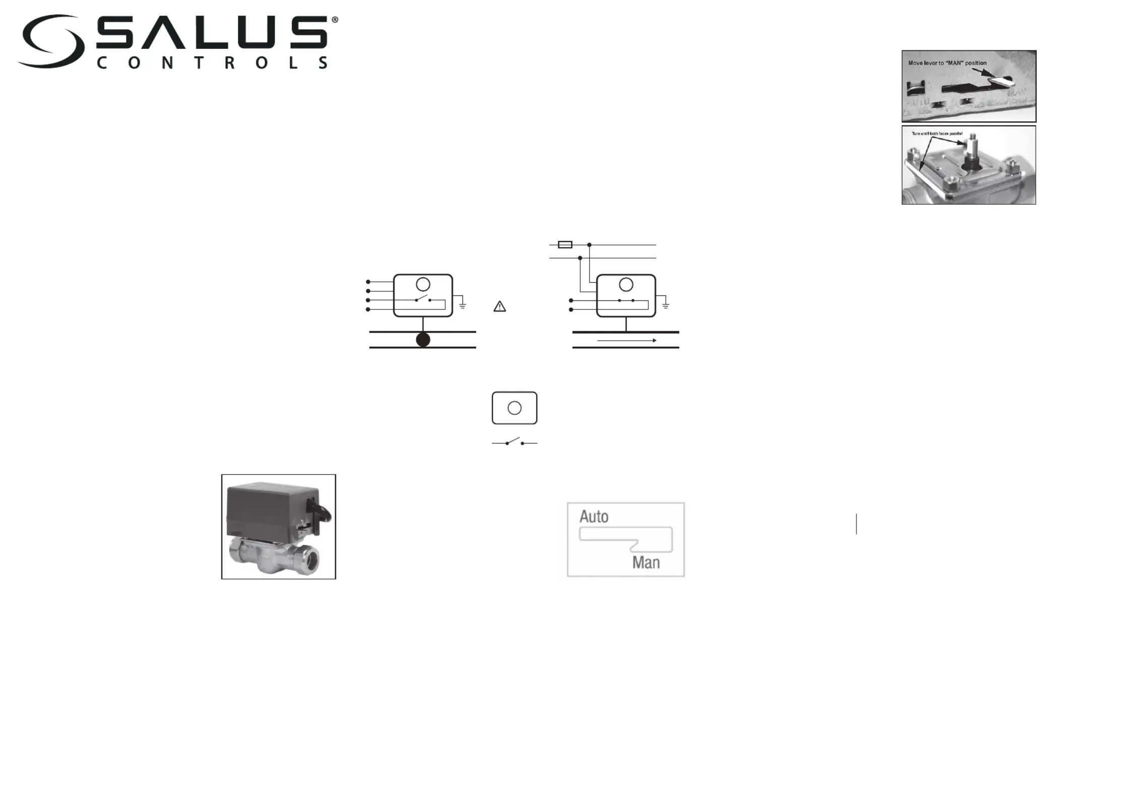
ACTUATOR REMOVAL AND REFITTING
The valve actuator can be removed or refitted without having to disturb the valve installation.
Removal:
1.Remove actuator cover
2. Lock lever in ‘MAN’ position
3 Loosen 2 securing screws
4. Lift actuator from valve body.
Re-tting:
1.Remove actuator cover
2. Lock lever in ‘MAN’ position
3. Turn valve stem to parallel position
as indicated
4. Push actuator onto valve
5. Tighten 2 securing screws
6.Release lever and allow to travel back to ‘AUTO’
Note:Do not attempt to dismantle the actuator assembly as it contains no user serviceable parts
– dismantling or tampering with the actuator assembly will invalidate the product warranty.
MAINTENANCE
The Motorised Valve requires no special maintenance. Periodically, the outer casing can be
wiped clean using a dry cloth (please DO NOT use solvents, polishes, detergents or abrasive
cleaners, as these can damage the Motorised Valve).
There are no user serviceable parts within the unit; any servicing or repairs should only be carried
out by SALUS Controls or their appointed agents.
Should the Motorised Valve fail to function correctly, check:
•The heating system is switched on.
•The lever is not latched in the MANUAL position.
PRODUCT SPECIFICATION
Model: 2 port motorized valve PMV21/22/24/28
Type: Motorised valve designed for domestic heating applications.
Electrical
Switching Voltage: 230V AC / 50Hz
Power Consumption: 6W
Response
Opening: 14 seconds
Closing: 3 seconds
Dierential Pressure
Pipe size 2 Way
22mm 0.8 bar
28mm 0.6 bar
Max Static Pressure: 8.6 bar
Flow coecient
PMV21 1” = 8.6 PMV24 3/4” = 6.9
PMV22 22mm = 6.9 PMV28 28mm = 8.6
Operating Temperatures
Min Fluid Temperature: 5 ºC
Max Fluid Temperature: 88 ºC
Environment
Operating Temperature: -10 ºC to + 60 ºC
Storage Temperature: - 20 ºC to + 65 ºC
Protection class: IP20
Do not restore the mains supply to the system until all associated items are fully installed.
NOTE: All electrical installation work should be carried out by a suitably qualified Electrician or
other competent person. If you are not sure how to install this motorised valve consult either
with a qualified electrician, heating engineer or your boiler / heating system supplier for advice
on how to continue.
Electrical Connection
The electrical connections to the motorised valve are made using the pre-wired cable. This
simplifies installation, as no connections need to be made to the actuator itself. The connecting
cable uses industry standard colours, and the connection details are shown below:
MANUAL LEVER
There is a lever on the side of the actuator cover: this
lever allows manual operation of the valve, e.g. for
refilling and draining of the system or if the actuator fails.
For two way valves, the lever allows the valve to be kept
open; with three way valves the lever allows both ports
A and B to be open at the same time.
To manually operate the valve, gently push the lever forward and latch it in the MAN position.
The valve will automatically return to AUTO when the actuator is powered up again.
NOTE: Push the manual lever slowly to prevent damage to the actuator motor and gear system.
The valve should be in manual position to be fitted.
Control wire (Power Supply AC 230V) Brown - Live. Blue - Neutral.
Close valve (no water flow): Brown 0V, Blue is N
Open valve (water flow): Brown 230Vac, Blue is N
Auxiliary switch output (COM, NO) Orange = COM. Grey = NO
When valve is open, orange and grey, AUX switch is closed. When valve is closed, orange and grey,
AUX switch is open. Yellow/Green wire is for earth.
2 PORT MOTORISED VALVE
PMV21 (1”) PMV22 (22 mm) PMV 24 (3/4”) PMV28 (28 mm)
P
RODUCER:
SALUS Controls Plc Units 8-10 Northfield Business Park Forge
Way, Parkgate, Rotherham S60 1SD, United Kingdom
www.saluscontrols.com
AUTOMAN
OPEN
Note: For basic diverter valve applications please isolate/Disregard the orange and Gray wires.
3/4” 0.8 bar
1” 0.6 bar
Description:
BR - brown wire
BL - blue wire
OR - orange wire
GR - gray wire
PE - earth
- valve actuator
- NO/COM switch output
M
MAX
3A
L
230V AC
N
BR
BL
OR
GR
COM
NO
PE
AB
M
STYKI
PE
BR
BL
OR
GR
AB
M
NO CONNECTION
NO FLOW
VOLTAGE FREE
TERMINALS
A -> B FLOW
Produktspezifikationen
| Marke: | Salus |
| Kategorie: | Nicht kategorisiert |
| Modell: | PMV21 |
Brauchst du Hilfe?
Wenn Sie Hilfe mit Salus PMV21 benötigen, stellen Sie unten eine Frage und andere Benutzer werden Ihnen antworten
Bedienungsanleitung Nicht kategorisiert Salus

10 Oktober 2025
22 August 2025
21 August 2025
15 August 2025
14 August 2025
14 August 2025
13 August 2025
13 August 2025
2 August 2025
1 August 2025
Bedienungsanleitung Nicht kategorisiert
Neueste Bedienungsanleitung für -Kategorien-
3 April 2026
3 April 2026
3 April 2026
3 April 2026
3 April 2026
3 April 2026
3 April 2026
3 April 2026
3 April 2026
3 April 2026