Sauermann ATE 310 Bedienungsanleitung
Sauermann Nicht kategorisiert ATE 310
Lies die bedienungsanleitung für Sauermann ATE 310 (4 Seiten) kostenlos online; sie gehört zur Kategorie Nicht kategorisiert. Dieses Handbuch wurde von 14 Personen als hilfreich bewertet und erhielt im Schnitt 4.1 Sterne aus 3 Bewertungen. Hast du eine Frage zu Sauermann ATE 310 oder möchtest du andere Nutzer dieses Produkts befragen? Stelle eine Frage
Seite 1/4
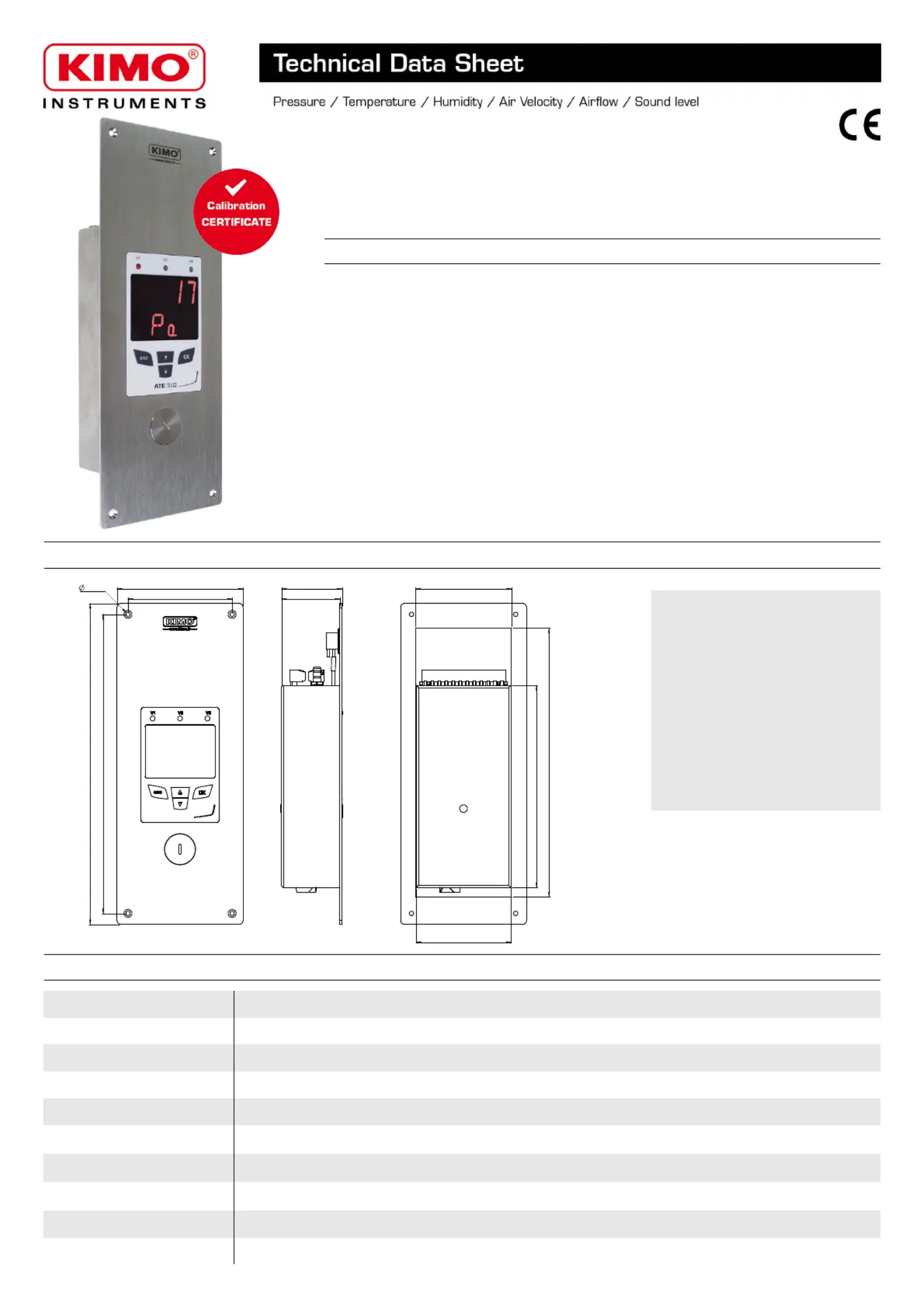
Flush-mount multifunction display unit
ATE 310
KEY POINTS
Front face
Brushed stainless steel 316 L
Back housing
Flush-mount in stainless steel 304 L
Protection
IP65 in front face
Weight
585 g
●
Alternating display of 1 to 3 parameters
●
3 audible and visual alarms
●
Configuration keyboard and acknoledgment of the alarm on the front face
●
3 analogue inputs 0-5/10 V or 0/4-20 mA
●
Ethernet communication (option)
●
RS485 MODBUS protocol communication
●
30 pre-programmed units and configurable units
●
Front face made of brushed stainless steel with electroluminescent display
FEATURES OF THE HOUSING
DISPLAY FEATURES
DisplayElectroluminescent alphanumeric (38 x 48 mm). Protection glass in red inactinic PMMA .
First line (measurement)4 digits of 8 segments each. Size: 14 x 48 mm.
Second line (unit)4 digits of 14 segments each. Size: 14 x 48 mm.
Comma positionConfigurable: 0 / 0.0 / 0.00
Value of the measurementFrom -9.99 to 99.99 and from -999 to 999
Accuracy*±0.1% of reading ±1 digit
Number of channelsFrom 1 to 3 ways alternating
Location of channelsBy red Led V1, V2 and V3
Available units30 pre-programmed units (see table) and configurable units
Response time< 1 second
*All accuracies indicated in this document were stated in laboratory conditions and can be guaranteed for measurements carried out in the same conditions, or carried out with calibration compensation.
234 mm
92 mm
44 mm
42.5 mm
70 mm
196 mm
3.2 mm
218 mm
76 mm
69 mm
147.3 mm
Produktspezifikationen
| Marke: | Sauermann |
| Kategorie: | Nicht kategorisiert |
| Modell: | ATE 310 |
Brauchst du Hilfe?
Wenn Sie Hilfe mit Sauermann ATE 310 benötigen, stellen Sie unten eine Frage und andere Benutzer werden Ihnen antworten
Bedienungsanleitung Nicht kategorisiert Sauermann

25 September 2025
28 August 2025
28 August 2025
28 August 2025
28 August 2025
27 August 2025
27 August 2025
27 August 2025
27 August 2025
27 August 2025
Bedienungsanleitung Nicht kategorisiert
Neueste Bedienungsanleitung für -Kategorien-
3 April 2026
3 April 2026
3 April 2026
3 April 2026
3 April 2026
3 April 2026
3 April 2026
3 April 2026
3 April 2026
3 April 2026