Silent Knight SK-ISO Bedienungsanleitung
Silent Knight Rauchmelder SK-ISO
Lies die bedienungsanleitung für Silent Knight SK-ISO (1 Seiten) kostenlos online; sie gehört zur Kategorie Rauchmelder. Dieses Handbuch wurde von 12 Personen als hilfreich bewertet und erhielt im Schnitt 4.4 Sterne aus 2 Bewertungen. Hast du eine Frage zu Silent Knight SK-ISO oder möchtest du andere Nutzer dieses Produkts befragen? Stelle eine Frage
Seite 1/1
SK-460-010 1 I56-3445-001
©2009 Honeywell International Inc.
INSTALLATION AND MAINTENANCE INSTRUCTIONS
SK-ISO Fault Isolator Module
I56-3445-001
SPECIFICATIONS
Normal Operating Voltage: 15-32 VDC
Stand-By Current: 450µA (not isolating, relay closed)
Temperature Range: 32°F to 120°F (0°C to 49°C)
Humidity: 10% to 93% Non-condensing
Dimensions: 4
1
/˝ H × 4˝ W × 2
1
/˝ D (Mounts to a 4˝ square by 24
1
/˝ deep box) 8
FAULT ISOLATOR
MODULE
1 (-)
2 (+)
3 (-)
4 (+)
UL LISTED COMPATIBLE
CONTROL PANEL
FAULT ISOLATOR
MODULE
1 (-)
2 (+)
3 (-)
4 (+)
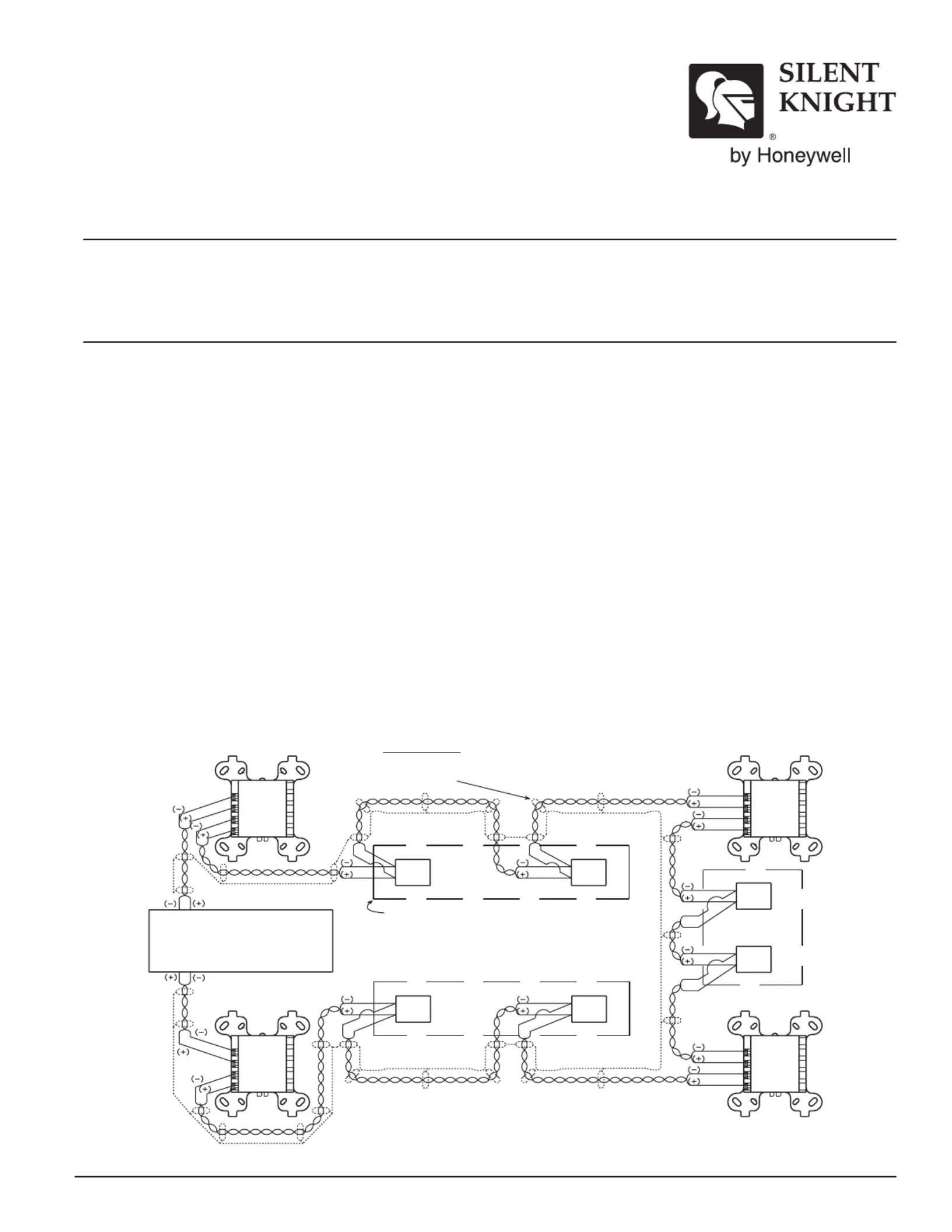
SIGNAL LINE CIRCUI(SLC)T
32 VDC MAX.
SHIELDED-TWISTED IRPA
IS RECOMMENDED
GROUPS OF DEVICES ARE SEPERATED BY FAULISOLAT TOR
MODULES. ANY COMBINATION OF COMPIBLE, LISTEDAT
DEVICES MAY BE CIRCUIWITHIN THAT T GROUP.
A PAIR OF FAULT ISOLATOR MODULES WILL DISCONNECT A
GROUP OF DEVICES IF A SHORCIRCUIOCCURS ON THET T
SIGNALING LINE CIRCUITHAT WITHIN T GROUP.
1 (-)
2 (+)
1 (-)
2 (+)
1 (-)
2 (+)
1 (-)
2 (+)
ALL WIRING SHOWN IS SUPERVISED.
1 (-)
2 (+)
1 (-)
2 (+)
FAULT ISOLATOR
MODULE
FAULT ISOLATOR
MODULE
1 (-)
2 (+)
3 (-)
4 (+)
1 (-)
2 (+)
3 (-)
4 (+)
FIGURE 1. SK-ISO FAULT ISOLATOR MODULE WIRING DIAGRAM
This information is included as a quick reference installation guide. Refer to
the appropriate Silent Knight Installation Manual for detailed system informa-
tion. If the modules will be installed in an existing operational system, inform
the operator and local authority that the system will be temporarily out of
service. Disconnect power to the control panel before installing the modules.
NOTICE: This manual should be left with the owner/user of this equipment.
GENERAL DESCRIPTION
SK-ISO FAULT ISOLATOR MODULES enable part of the communications loop
to continue operating when a short circuit occurs on it. An LED indicator
blinks in the normal condition and turns on during a short circuit condition.
The module will automatically restore the entire communications loop to the
normal condition when the short circuit is removed.
COMPATIBILITY REQUIREMENTS
To ensure proper operation, these modules shall be connected to compatible
Silent Knight system control panels only.
NOTE: In general, up to 25 addressable devices may be grouped between iso-
lator modules.
MOUNTING
SK-ISO modules mount directly to 4 inch square electrical boxes. The box
must have a minimum depth of 21/8˝.
WIRING
NOTE: All wiring must conform to applicable local codes, ordinances, and
regulations.
1. Install module wiring in accordance with the job drawings and the wir-
ing diagrams in Figure 1.
2. Secure module to electrical box (supplied by installer).
C0802-01
12 Clintonville Road, Northford, CT 06472
203.484.7161; Fax: 203.484.7118
www.silentknight.com
Produktspezifikationen
| Marke: | Silent Knight |
| Kategorie: | Rauchmelder |
| Modell: | SK-ISO |
Brauchst du Hilfe?
Wenn Sie Hilfe mit Silent Knight SK-ISO benötigen, stellen Sie unten eine Frage und andere Benutzer werden Ihnen antworten
Bedienungsanleitung Rauchmelder Silent Knight

31 August 2025
Bedienungsanleitung Rauchmelder
Neueste Bedienungsanleitung für -Kategorien-
26 März 2026
17 März 2026
10 März 2026
10 März 2026
8 März 2026
12 Januar 2026
10 Januar 2026
6 Januar 2026
30 Dezember 2026
29 Dezember 2026