Texas Instruments LM51501-Q1 Bedienungsanleitung
Texas Instruments Nicht kategorisiert LM51501-Q1
Lies die bedienungsanleitung für Texas Instruments LM51501-Q1 (53 Seiten) kostenlos online; sie gehört zur Kategorie Nicht kategorisiert. Dieses Handbuch wurde von 4 Personen als hilfreich bewertet und erhielt im Schnitt 5.0 Sterne aus 8 Bewertungen. Hast du eine Frage zu Texas Instruments LM51501-Q1 oder möchtest du andere Nutzer dieses Produkts befragen? Stelle eine Frage
Seite 1/53
LM51501-Q1 Wide VIN Automotive Low I
Q
Boost Controller
1 Features
•AEC-Q100 qualified:
–Device temperature grade 1: –40°C to +125°C
ambient operating temperature range
–Device HBM ESD classification level 2
–Device CDM ESD classification level C4B
•Functional Safety-Capable
–Documentation available to aid functional safety
system design
•Wide VIN input range from 1.5 V to 42 V when
VOUT ≥ 5 V (65-V absolute maximum)
•Low shutdown current (I
Q
≤ 5 µA)
•Low standby current (I
Q
≤ 15 µA)
•Four programmable output voltage options and
two selectable configurations
–6.0 V, 6.5 V, 9.5 V, or 11.5 V
–Start-stop or e-call configurations
•Adjustable switching frequency from 220 kHz to
2.3 MHz
•Automatic wake-up and standby mode transition
•Optional clock synchronization
•Boost status indicator
•1.5-A peak MOSFET gate driver
•Adjustable cycle-by-cycle current limit
•Thermal shutdown
•16-pin WQFN with wettable and non-wettable flank
options
•Create a custom design using the LM51501-Q1
with the WEBENCH
®
Power Designer
2 Applications
•Automotive start-stop system
•Automotive emergency call system
•Battery-powered boost converters
3 Description
The LM51501-Q1 is a wide input range automatic
boost controller. The device can be used to maintain a
stable output voltage during automotive cranking from
a vehicle battery or from a backup battery.
The LM51501-Q1 switching frequency is programmed
by a resistor from 220 kHz to 2.3 MHz. Fast switching
(≥ 2.2 MHz) minimizes AM band interference and
allows for a small solution size and fast transient
response.
The LM51501-Q1 operates in low I
Q
standby mode
when the input or output voltage is above the preset
standby thresholds and automatically wakes up when
the output voltage drops below the preset wake-up
threshold.
The device transitions in and out of low I
Q
standby
mode to extend battery life at light load. A single
resistor programs the target output regulation voltage
as well as the configuration. Additional features
include low shutdown current, boost status indicator,
adjustable cycle-by-cycle current limit, and thermal
shutdown. A status indicator can be used to control
a circuit to bypass the diode when the part is not
boosting in order to reduce power dissipation. In
E-call mode, the device can be used to control a
disconnect switch to protect the backup-battery.
Device Information
PART NUMBERPACKAGE
(1)
BODY SIZE (NOM)
LM51501-Q1WQFN (16)4.00 mm × 4.00 mm
(1)For all available packages, see the orderable addendum at
the end of the data sheet.
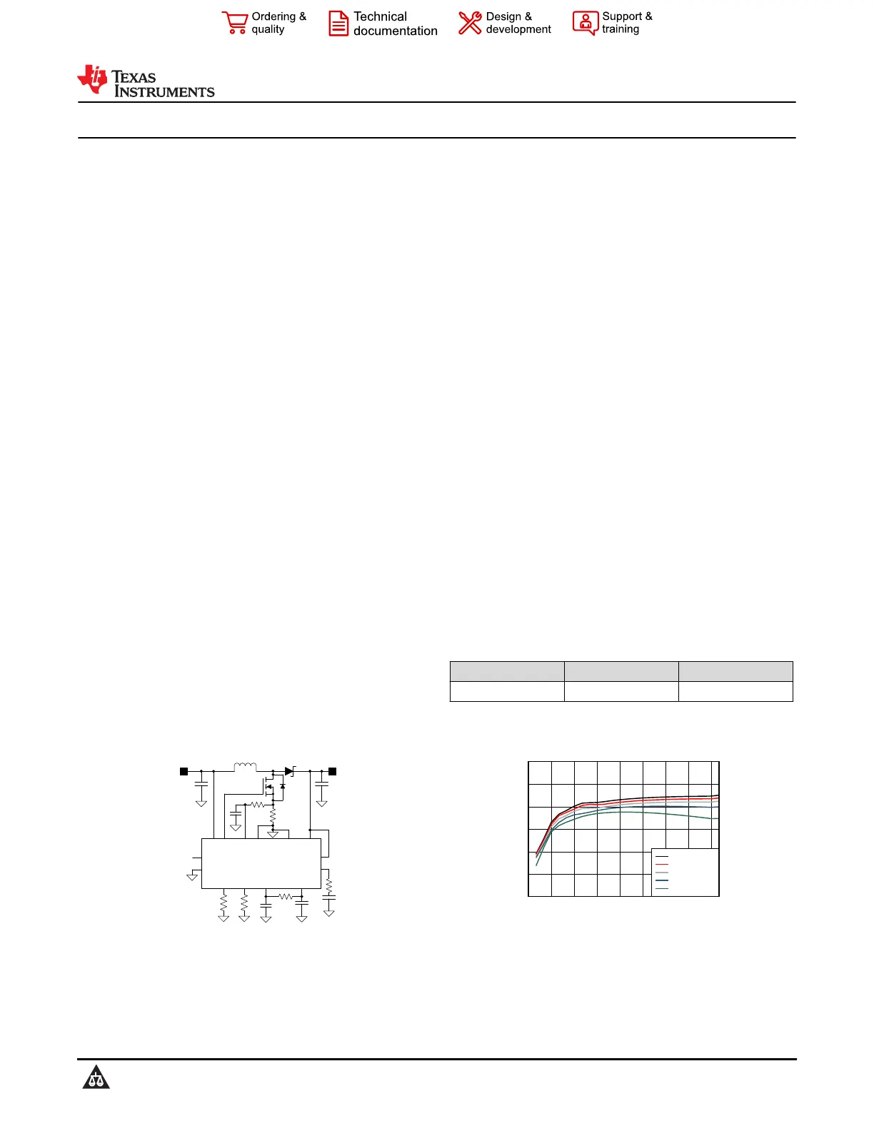
V
SUPPLY
V
LOAD
CSLO
VIN
VOUT
LM51501
AGND
VCC
COMP
RT
EN
STATUS
VSET
SYNC
AVCC
PGND
Typical Application Circuit
Load Current (A)
Efficiency (%)
00.30.60.91.21.51.82.12.4
70
75
80
85
90
95
100
D008
V
SUPPLY
=7.5V
V
SUPPLY
=6.5V
V
SUPPLY
=5.5V
V
SUPPLY
=4.5V
V
SUPPLY
=3.5V
Efficiency (V
LOAD
= 9.5 V, F
SW
= 440 kHz)
LM51501-Q1
SNVSAZ0C – MARCH 2018 – REVISED OCTOBER 2021
An IMPORTANT NOTICE at the end of this data sheet addresses availability, warranty, changes, use in safety-critical applications,
intellectual property matters and other important disclaimers. PRODUCTION DATA.
Produktspezifikationen
| Marke: | Texas Instruments |
| Kategorie: | Nicht kategorisiert |
| Modell: | LM51501-Q1 |
Brauchst du Hilfe?
Wenn Sie Hilfe mit Texas Instruments LM51501-Q1 benötigen, stellen Sie unten eine Frage und andere Benutzer werden Ihnen antworten
Bedienungsanleitung Nicht kategorisiert Texas Instruments

3 April 2026
3 April 2026
2 April 2026
2 April 2026
2 April 2026
2 April 2026
2 April 2026
2 April 2026
1 April 2026
1 April 2026
Bedienungsanleitung Nicht kategorisiert
Neueste Bedienungsanleitung für -Kategorien-
3 April 2026
3 April 2026
3 April 2026
3 April 2026
3 April 2026
3 April 2026
3 April 2026
3 April 2026
3 April 2026
3 April 2026