Texas Instruments LM5152-Q1 Bedienungsanleitung
Texas Instruments Nicht kategorisiert LM5152-Q1
Lies die bedienungsanleitung für Texas Instruments LM5152-Q1 (47 Seiten) kostenlos online; sie gehört zur Kategorie Nicht kategorisiert. Dieses Handbuch wurde von 2 Personen als hilfreich bewertet und erhielt im Schnitt 4.0 Sterne aus 5 Bewertungen. Hast du eine Frage zu Texas Instruments LM5152-Q1 oder möchtest du andere Nutzer dieses Produkts befragen? Stelle eine Frage
Seite 1/47
LM5152x-Q1 Automotive Low-I
Q
Synchronous Boost Controller for Start-Stop/Backup
Battery Power Supply
1 Features
•AEC-Q100 qualified for automotive applications
–Temperature grade 1: –40°C to +125°C, T
A
•Functional Safety-Capable
–Documentation available to aid functional safety
system design
•Suited for wide operating range automotive battery
powered applications
–3.8-V to 42-V input operating range
–Dynamically programmable V
OUT
from 5 V to
20 V (protection up to 57 V)
–Minimum boost input 0.8 V when BIAS ≥ 3.8 V
–Bypass operation when V
SUPPLY
> V
LOAD
(LM5152 only, see the device comparison
table)
•Minimized battery drain
–Shutdown current ≤ 3 μA
–Automatic mode transition
–Battery drain in deep sleep ≤ 11 μA (bypass
operation, charge pump off)
–Battery drain in deep sleep ≤ 33 μA (bypass
operation, charge pump on)
–BIAS I
Q
in sleep ≤ 13 μA (skip mode)
–Strong 5-V MOSFET drivers
•Small solution size and low cost
–2.2-MHz maximum switching frequency
–Internal boot diode
–Constant peak current limit over V
IN
–Supports DCR inductor current sensing
–QFN-20 with wettable flanks
•Avoid AM band interference and crosstalk
–Optional clock synchronization
–100-kHz to 2.2-MHz switching frequency
–Selectable switching mode (FPWM, diode
emulation, skip mode)
•EMI mitigation
–Optional programmable spread spectrum
–Lead-less package
•Programmability and flexibility
–Dynamic V
OUT
tracking
–Dynamic switching frequency programming
–Programmable line UVLO
–Adjustable soft start
–Adaptive dead time
–Boost STATUS indicator
•Integrated protection features
–Cycle-by-cycle peak current limit
–Overvoltage protection
–HB-SW short protection
–Thermal shutdown
2 Applications
•High power/high current automotive start-stop
application (head unit)
•Voltage stabilizer module
•Emergency call application
•Backup battery/super capacitor powered boost
converter
•Automotive redundant power supply
3 Description
The LM5152x-Q1 (LM5152-Q1 and LM51521-Q1)
device is a wide input range synchronous boost
controller that employs peak current mode control.
Device Information
PART NUMBERPACKAGE
(1)
BODY SIZE (NOM)
LM5152-Q1
QFN (20)3.5 mm × 3.5 mm
LM51521-Q1
(1)For all available packages, see the orderable addendum at
the end of the data sheet.
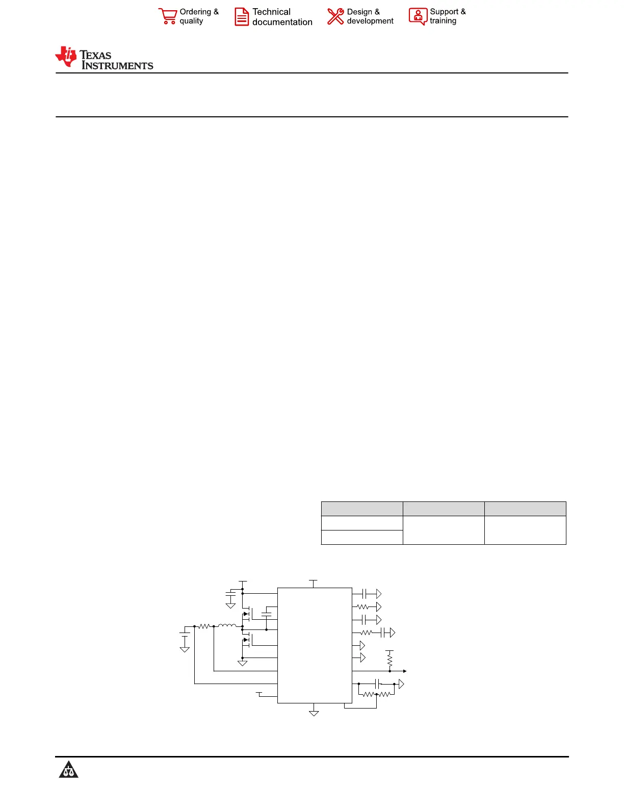
HO
HB
SW
CSN
BIASVCC
TRK
LO
RT
COMP
SS
CSP
PGND
AGND
UVLO
VOUT
V
LOAD
V
SUPPLY
V
SUPPLY
MODE
SYNC/DITHER
STATUS
VREF
Boost Status
Indicator to MCU
VDD(MCU)
V
LOAD
Typical Application
LM5152-Q1, LM51521-Q1
SLVSFF2A – FEBRUARY 2022 – REVISED APRIL 2022
An IMPORTANT NOTICE at the end of this data sheet addresses availability, warranty, changes, use in safety-critical applications,
intellectual property matters and other important disclaimers. PRODUCTION DATA.
Produktspezifikationen
| Marke: | Texas Instruments |
| Kategorie: | Nicht kategorisiert |
| Modell: | LM5152-Q1 |
Brauchst du Hilfe?
Wenn Sie Hilfe mit Texas Instruments LM5152-Q1 benötigen, stellen Sie unten eine Frage und andere Benutzer werden Ihnen antworten
Bedienungsanleitung Nicht kategorisiert Texas Instruments

3 April 2026
3 April 2026
2 April 2026
2 April 2026
2 April 2026
2 April 2026
2 April 2026
2 April 2026
1 April 2026
1 April 2026
Bedienungsanleitung Nicht kategorisiert
Neueste Bedienungsanleitung für -Kategorien-
3 April 2026
3 April 2026
3 April 2026
3 April 2026
3 April 2026
3 April 2026
3 April 2026
3 April 2026
3 April 2026
3 April 2026