Texas Instruments MAX3222E Bedienungsanleitung
Texas Instruments Nicht kategorisiert MAX3222E
Lies die bedienungsanleitung für Texas Instruments MAX3222E (24 Seiten) kostenlos online; sie gehört zur Kategorie Nicht kategorisiert. Dieses Handbuch wurde von 5 Personen als hilfreich bewertet und erhielt im Schnitt 4.4 Sterne aus 4 Bewertungen. Hast du eine Frage zu Texas Instruments MAX3222E oder möchtest du andere Nutzer dieses Produkts befragen? Stelle eine Frage
Seite 1/24
MAX3222E 3V to 5.5V Multichannel RS-232 Line Driver and Receiver With ±15kV ESD
Protection
1 Features
•ESD Protection for RS-232 bus pins
–±15kV Human-body model (HBM)
–±8kV IEC61000-4-2, Contact discharge
–±15kV IEC61000-4-2, Air-gap discharge
•Meets or exceeds the requirements of TIA/
EIA-232-F and ITU v.28 standards
•Operates with 3V to 5.5V V
CC
supply
•Operates up to 500kbit/s
•Two drivers and two receivers
•Low standby current: 1μA typical
•External capacitors: 4 × 0.1μF
•Accepts 5V logic input with 3.3V supply
•Alternative high-speed pin-compatible device
(1Mbit/s) for SNx5C3222E
2 Applications
•Industrial PCs
•Wired networking
•Data center and networking equipment
•Notebooks
•Hand-held equipment
3 Description
The MAX3222E consists of two line drivers, two line
receivers, and a dual charge-pump circuit with ±15kV
ESD protection pin to pin (serial-port connection pins,
including GND).
The device meets the requirements of TIA/EIA-232-
F and provides the electrical interface between
an asynchronous communication controller and the
serial-port connector. The charge pump and four small
external capacitors allow operation from a single 3V
to 5.5V supply. The device operates at typical data
signaling rates up to 500kbit/s and a maximum of
30V/μs driver output slew rate.
The MAX3222E can be placed in the power-down
mode by setting the power-down ( PWRDOWN) input
low, which draws only 1μA from the power supply.
When the device is powered down, the receivers
remain active while the drivers are placed in the
high-impedance state. Also, during power down, the
onboard charge pump is disabled; V+ is lowered to
V
CC
, and V– is raised toward GND. Receiver outputs
also can be placed in the high-impedance state by
setting enable ( EN) high.
Package Information
PART NUMBERPACKAGE
(1)
PACKAGE SIZE
(2)
MAX3222E
DB (SSOP, 20)7.2mm x 7.8mm
DW (SOIC, 20)12.8mm x 10.3mm
PW (TSSOP, 20)6.5mm x 6.4mm
DGS (VSSOP, 20)5.1mm x 4.9mm
(1)For more information, see Section 11.
(2)The package size (length × width) is a nominal value and
includes pins, where applicable.
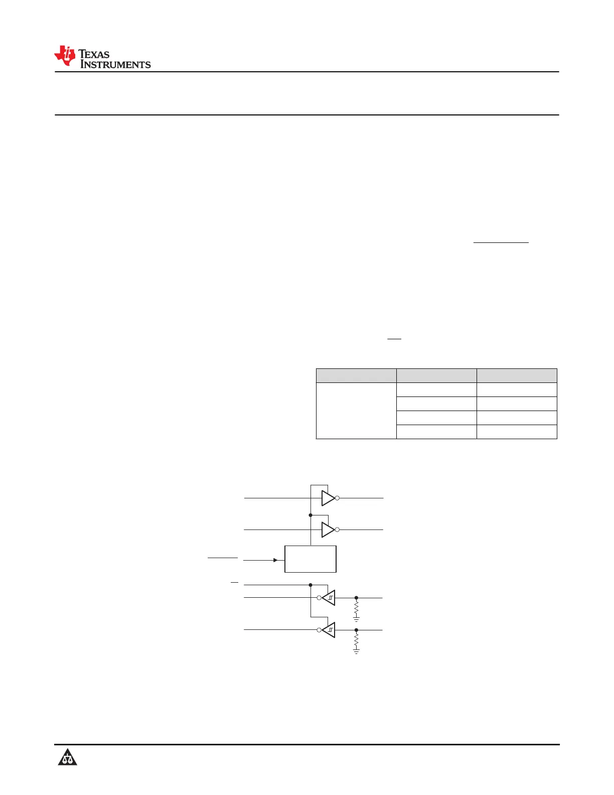
DIN2
DOUT2
128
Powerdown
RIN1
16
20
15
PWRDOWN
ROUT1
DIN1
DOUT1
1317
RIN2
910
ROUT2
1
EN
5 kW
5 kW
Pin numbers are for the DB, DW, and PW packages.
Logic Diagram (Positive Logic)
MAX3222E
SLLS708E – JANUARY 2006 – REVISED DECEMBER 2024
An IMPORTANT NOTICE at the end of this data sheet addresses availability, warranty, changes, use in safety-critical applications,
intellectual property matters and other important disclaimers. PRODUCTION DATA.
Produktspezifikationen
| Marke: | Texas Instruments |
| Kategorie: | Nicht kategorisiert |
| Modell: | MAX3222E |
Brauchst du Hilfe?
Wenn Sie Hilfe mit Texas Instruments MAX3222E benötigen, stellen Sie unten eine Frage und andere Benutzer werden Ihnen antworten
Bedienungsanleitung Nicht kategorisiert Texas Instruments

3 April 2026
3 April 2026
2 April 2026
2 April 2026
2 April 2026
2 April 2026
2 April 2026
2 April 2026
1 April 2026
1 April 2026
Bedienungsanleitung Nicht kategorisiert
Neueste Bedienungsanleitung für -Kategorien-
3 April 2026
3 April 2026
3 April 2026
3 April 2026
3 April 2026
3 April 2026
3 April 2026
3 April 2026
3 April 2026
3 April 2026