Texas Instruments MAX4596 Bedienungsanleitung
Texas Instruments Nicht kategorisiert MAX4596
Lies die bedienungsanleitung für Texas Instruments MAX4596 (22 Seiten) kostenlos online; sie gehört zur Kategorie Nicht kategorisiert. Dieses Handbuch wurde von 10 Personen als hilfreich bewertet und erhielt im Schnitt 5.0 Sterne aus 6 Bewertungen. Hast du eine Frage zu Texas Instruments MAX4596 oder möchtest du andere Nutzer dieses Produkts befragen? Stelle eine Frage
Seite 1/22
W
SLLS641 – JANUARY 2005
Description
The MAX4596 is a single-pole single-throw (SPST)
analog switch that is designed to operate from 2 V to
5 V. This device can handle both digital and analog
signals, and signals up to V
+
(peak) can be transmitted
in either direction.
Applications
DSample-and-Hold Circuits
DBattery-Powered Equipment
DAudio and Video Signal Routing
DCommunication Circuits
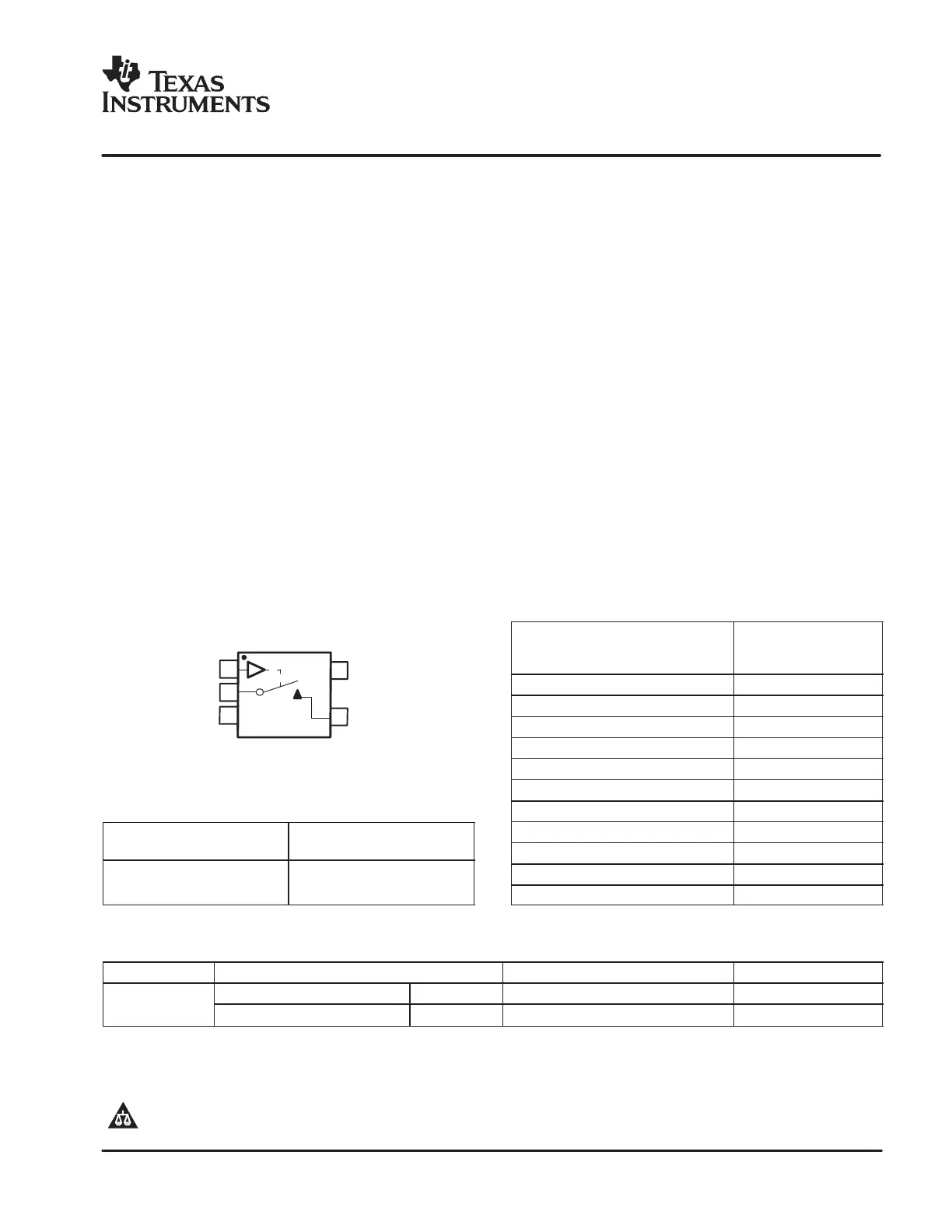
SOT-23 OR SC-70 PACKAGE
(TOP VIEW)
1
2
3
5
4
IN
COM
GND
NO
V
+
FUNCTION TABLE
IN
NO TO COM,
COM TO NO
LOFF
HON
Features
DLow ON-State Resistance (10 W)
DON-State Resistance Flatness (1.5 W)
DControl Inputs Are 5.5-V Tolerant
DLow Charge Injection (5 pC Max)
D300-MHz −3-dB Bandwidth at 255C
DLow Total Harmonic Distortion (THD) (0.05%)
D2-V to 5.5-V Single-Supply Operation
DSpecified at 5-V and 3.3-V Nodes
D−83-dB OFF Isolation at 1 MHz
DLatch-Up Performance Exceeds 100 mA Per
JESD 78, Class II
D0.5-nA Max OFF Leakage
DESD Performance Tested Per JESD 22
− 2000-V Human-Body Model
(A114-B, Class II)
− 1000-V Charged-Device Model (C101)
DTTL/CMOS-Logic Compatible
Summary of Characteristics
V
+
= 5 V, T
A
= 25°C
Configuration
Single Pole
Single Throw
(SPST)
Number of channels1
ON-state resistance (r
on
)10 Ω
ON-state resistance flatness (r
on(flat)
)1.5 Ω
Turn-on/turn-off time (t
ON
/t
OFF
)35 ns/40 ns
Charge injection (Q
C
)5 pC
Bandwidth (BW)300 MHz
OFF isolation (O
ISO
)−83 dB at 1 MHz
Total harmonic distortion (THD)0.05%
Leakage current (I
COM(OFF)
/I
NO(OFF)
)±0.05 nA
Power-supply current (I
+
)1 µA
Package option5-pin SOT-23 or SC-70
ORDERING INFORMATION
T
A
PACKAGE
(1)
ORDERABLE PART NUMBERTOP-SIDE MARKING
(2)
−40°C to 85°C
SOT (SOT-23) − DBVTape and reelMAX4596DBVR6SB_
−40
°
C to 85
°
C
SOT (SC−70) − DCKTape and reelMAX4596DCKRSB_
(1)
Package drawings, standard packing quantities, thermal data, symbolization, and PCB design guidelines are available at www.ti.com/sc/package.
(2)
DBV/DCK: The actual top-side marking has one additional character that designates the assembly/test site.
Please be aware that an important notice concerning availability, standard warranty, and use in critical applications of TexasInstruments
semiconductor products and disclaimers thereto appears at the end of this data sheet.
www.ti.com
Copyright 2005, Texas Instruments Incorporated
!" # $%&" !# '%()$!" *!"&+
*%$"# $ " #'&$$!"# '& ",& "&# &-!# #"%&"#
#"!*!* .!!"/+ *%$" '$&##0 *&# " &$&##!)/ $)%*&
"&#"0 !)) '!!&"&#+
Produktspezifikationen
| Marke: | Texas Instruments |
| Kategorie: | Nicht kategorisiert |
| Modell: | MAX4596 |
Brauchst du Hilfe?
Wenn Sie Hilfe mit Texas Instruments MAX4596 benötigen, stellen Sie unten eine Frage und andere Benutzer werden Ihnen antworten
Bedienungsanleitung Nicht kategorisiert Texas Instruments

3 April 2026
3 April 2026
2 April 2026
2 April 2026
2 April 2026
2 April 2026
2 April 2026
2 April 2026
1 April 2026
1 April 2026
Bedienungsanleitung Nicht kategorisiert
Neueste Bedienungsanleitung für -Kategorien-
3 April 2026
3 April 2026
3 April 2026
3 April 2026
3 April 2026
3 April 2026
3 April 2026
3 April 2026
3 April 2026
3 April 2026