Camille Bauer SINEAX VS40 Bedienungsanleitung
Camille Bauer Audio/Video-Konverter SINEAX VS40
Lies die bedienungsanleitung für Camille Bauer SINEAX VS40 (2 Seiten) kostenlos online; sie gehört zur Kategorie Audio/Video-Konverter. Dieses Handbuch wurde von 21 Personen als hilfreich bewertet und erhielt im Schnitt 4.4 Sterne aus 9 Bewertungen. Hast du eine Frage zu Camille Bauer SINEAX VS40 oder möchtest du andere Nutzer dieses Produkts befragen? Stelle eine Frage
Seite 1/2
Eingang:
Stromfühler:
Widerstand der Kabel:
Messbereich:
Widerstandsbereich:
Min. Span:
Ausgangsspannung:
Ausgangsstrom:
Ausgang bei
Bereichsüberschreitung:
Ausgang bei Defekt:
StromAusgangsschutz:
D
SINEAX VS40 - 162959
TEMPERATURE-SIGNALWANDLER FÜR PT100 MIT GALV. TRENNUNG
Allgemeine Beschreibung
Der Wandler VS40 wandelt ein von einem mit 2, 3 oder 4 Leitern angeschlossenen
Fühler PT100 (EN 60 751) gemessenesTemperatursignal in ein genormtes
Spannungs- oder Stromsignal.
Die Eigenschaften des Wandlers sind die stark begrenztenAbmessungen (6,2 mm), die
Verankerung auf DIN-Schiene zu 35 mm, die Möglichkeit der Speisung über Bus, die
schnellenAnschlüsse über Federklemmen, die galvanische 3-WegeTrennung und die
Konfigurierbarkeit vor Ort über DIP-Schalter.
Technische Eigenschaften
Spannungsversorgung:
Leistungsaufnahme:
19,2..30 Vdc
max. 21 mAbei 24 Vdc
Fühler PT100, EN 60751/A2 (ITS90)
Anschluss mit 2, 3 oder 4 Leitern
< 900 uAkonstant
max 20je Leiter
-150..650 °C
20..350
50 °C
Ω
Ω
0 - 5 Vdc, 1 - 5 Vdc, 0 - 10 Vdc und 10 - 0 Vdc
Min. Lastwiderstand 2 K
0 - 20 mA, 4 - 20 mA, 20 - 0 mAund 20 - 4 mA
Max. Lastwiderstand 500
102,5% des Skalenbereiches (sieheTabelle auf Seite 5)
105% des Skalenbereiches (sieheTabelle auf Seite 5)
Ω
Ω
annähernd 25 mA
Übertragungsfehler:
Temperaturkoeffizient:
Antwortzeit (10 - 90%):
0,1 % (max. Bereich), oder
(40 K / D+ 0,05) % (Messbereich)
< 50 ms (ohne Filter)
< 200 ms (mit Rejektionsfilter 50 Hz)
temp
100 ppm
Isolierungsspannung:
Schutzart:
Umgebungsbedingungen:
Lagertemperatur:
LED-Anzeigen:
Anschlüsse:
Leiterquerschnitt:
Abisolierung der Leiter:
Gehäuse:
Abmessungen, Gewicht:
1,5 KV (50 Hz für 1 Min.)
Temperatur -20..+65°C
30..90 % bei 40°C, nicht kondensierend.
Anzeigefehler, defekterAnschluss, interner Defekt
Federklemmen
IP20
Luftfeuchtigkeit
-40..+85 °C
0,2..2,5 mm
8 mm
2
PBT(schwarze Farbe)
6,2 x 93,1 x 102,5 mm, 50 g.
SINEAX VS40SINEAX VS40SINEAX VS40SINEAX VS40
SINEAX VS40SINEAX VS40SINEAX VS40SINEAX VS40
DEUTSCH - 1/8
DEUTSCH - 2/8DEUTSCH - 4/8DEUTSCH - 6/8DEUTSCH - 8/8
DEUTSCH - 3/8DEUTSCH - 5/8DEUTSCH - 7/8
Einsatz des CB-Power-Bus
1 - Setzen Sie die CB-Power-Bus-Anschlüsse zusammen, um die erforderlicheAnzahl
von positionen zu erzielen (jeder CB-Power-Bus gestattet dieAufnahme von 2
Modulen)
2 - Setzen Sie den CB-Power-Bus in die Schiene ein; setzen Sie ihn dazu auf
der oberen Seite ein und drehen Sie ihn nach unten
WICHTIG: Schenken Sie der Position der vorstehenden Klemmen der Busschiene eine
erhöhteAufmerksamkeit. Der CB-Power-Bus muss so in die DIN-Schiene gesetzt
werden, so dass die vorstehenden Klemmen links liegen (wie im Bild), anderenfalls
sind die Wandler kopfüber montiert.
Eingang
Das Modul ist für denAnschluss an einenTemperaturfühler PT100 (EN 60 751) über
2, 3 oder 4 Leiter geeignet.
Anschluss, der bei Entfernungen von weniger als 10 m zwischen Modul und Fühler
verwendet wird; dabei muss berücksichtigt werden, dass ein Messfehler erzeugt wird,
der dem Widerstand der beiden Verbindungskabel entspricht.
DIP-Schalter SW1-1 in Position 1 (AN) (2 / 4 Draht).
Mit Brücken zwischen Klemmen 1 und 2 und Klemmen 3 und 4.
Anschluss, der bei Entfernungen von mehr als 10 m zwischen Modul und Fühler
verwendet wird, da das Instrument eine Kompensierung des Widerstands der
Anschlusskabel vornimmt. Für eine korrekte Kompensierung muss der Widerstand der
beiden Kabel gleich sein, da das Instrument den Widerstand eines Kabels misst und
voraussetzt, dass der Widerstand des anderen Kabels gleich ist.
DIP-Schalter SW1-1 in Position 0 (AUS) (3 Draht).
Mit Brücke zwischen den Klemmen 3 und 4.
Anschluss, der bei Entfernungen von mehr als 10 m zwischen Modul und Fühler
verwendet wird, gestattet die Erzielung der max. Präzision, da das Instrument die
Kompensierung des Widerstands der Verbindungskabel vornimmt. Bei diesem
Anschluss besteht das Problem des Widerstands zwischen den beiden Kabeln nicht,
da das Instrument den Widerstand beider Kabel misst.
DIP-Schalter SW1-1 in Position 1 (AN) (2 / 4 Draht).
2-DrahtAnschluss
3-DrahtAnschluss
4-DrahtAnschluss
Anweisungen zur Installation
Das Modul ist für die Montage auf Schienen nach DIN 46277 ausgelegt. Für eine
bessere Belüftung des Moduls empfehlen wir die Montage in vertikaler Stellung sowie
die Vermeidung der Positionierung in Kanälen oder von sonstigen Gegenständen, die
eine Belüftung behindern.
VermeidenSiedieInstallationdesModulsüberGeräten,dieWärmeerzeugen;wir
empfehlendieInstallationimunterenBereichderSchalttafeloderdesGehäuses.
Wir empfehlen die Montage auf der Schiene mit dem entsprechendenAnschlussbus
(Bestellnr. CB-Power-Bus), der dasAnschließen der Speisung an jedes einzelne Modul
überflüssig macht.
Normen:
EN50081-2 (elektromagnetische Emission, industrielle
Umgebung)
EN50082-2 (elektromagnetische Immunität, industrielle
Umgebung)
EN61010-1 (Sicherheit)
Alle Schaltungen müssen mit doppelter Isolierung gegen
Schaltungen mit gefährlicher Spannung isoliert werden.
Der Speisungstransformator muss der Norm EN60742:
“Isolierungstransformatoren und
Sicherheitstransformatoren”entsprechen.
1 - Setzen Sie das Modul in den oberen
Teil der Schiene ein
2 - Drücken Sie das Modul nach unten
1 - Hebeln Sie mit einem Schraubenzieher
(wie auf derAbbildung gezeigt)
2 - Drehen Sie das Modul nach oben
Montage des Moduls in der Schiene
Entfernung des Moduls von der Schiene
ELEKTRISCHE VERBINDUNG
8 mm
0,2..2,5 mm
2
DasModulbesitztFederklemmenfürdieelektrischen
Anschlüsse.
NehmenSiebeidenAnschlüssenaufdiefolgenden
AnweisungenBezug:
1EntfernenSie0,8cmderIsolierungamEndeder
Kabel
2FührenSieeinenSchraubenzieherindie
quadratischeÖffnungeinunddrückenSieihn,bissich
dieFederöffnet,diedasKabelblockiert
3FührenSiedasKabelindierundeÖffnungein
4 Ziehen Sie den Schraubenzieher heraus und
überprüfen Sie, ob das Kabel sicher in der Klemme
befestigt ist.
Spannungsversorgung
Es bestehen verschiedene Möglichkeiten für die
Speisung der Module der Serie VS.
1 - Direkte Speisung der Module durchAnschluss
der Speisung von 24 Vdc direkt an die Klemmen 7
(+) und 8 (-) jedes einzelnen Moduls
15
6
7
8
2
3
4
POWER
SUPPLY
OUTPUT
INPUT
19.2..30 Vdc
+
-
2-VerwendungdesZubehörartikelsCB-Power-BusfürdieVerteilungderSpeisungandie
ModuleüberBus,wodurchdieSpeisungjedeseinzelnenModulsüberflüssigwird.
Über den Bus können alle Module gespeist werden; die Gesamtleistungsaufnahme des
Busses muss unter 400 mAliegen. Bei größeren Leistungsaufnahmen können die
Module beschädigt werden. In die Speisung muss eine entsprechend bemessene
Sicherung in Reihe eingesetzt werden.
3-VerwendungdesZubehörartikelsCB-Power-BusfürdieDistributionderSpeisungder
ModuleüberBussowiedesZubehörartikelsVS70fürdenAnschlussandieSpeisung.
DasVS70isteinModulmiteinerBreitevon6,2mm,daseineReihevon
SchutzschaltungenzumSchutzderüberdenBusangeschlossenenModulegegen
eventuelleÜberspannungenaufweist.
Der Bus kann über ein Modul VS70 gespeist werden, falls die
Gesamtleistungsaufnahme des Busses unter 1,5Aliegt. Bei höheren
Leistungsaufnahmen können das Modul oder der Bus beschädigt werden. In die
Speisung muss eine entsprechend bemessene Sicherung in Reihe eingesetzt werden.
Ausgang
Spannungsanschluss - Stromanschluss (Fremdstrom)
Anmerkung: Zur Reduzierung der Dissipation des Instruments sollte der
Spannungsausgang verwendet oder eine Last von >am Stromausgang
garantiert werden.
250Ω
15
6
7
8
2
3
4
POWER
SUPPLY
OUTPUT
INPUT
V / I
+
-
Anzeige mit LED auf der Front
LEDBedeutung
Schnell blinkend
1 Impuls/sec
Interne Fehlfunktion
Langsam blinkend
3 Impulse/sec
DIP-Schalter Einstellungsfehler
Dauerhaft anPT100 Verdrahtung Fehlfunktion.
3ter Drahtwiderstand Bereichsüberschreitung.
- Schließen Sie nie die Speisung direkt am Bus der DIN-Schiene an.
- Greifen Sie die Speisung weder direkt, noch über die Klemmen der Module
ab.
!
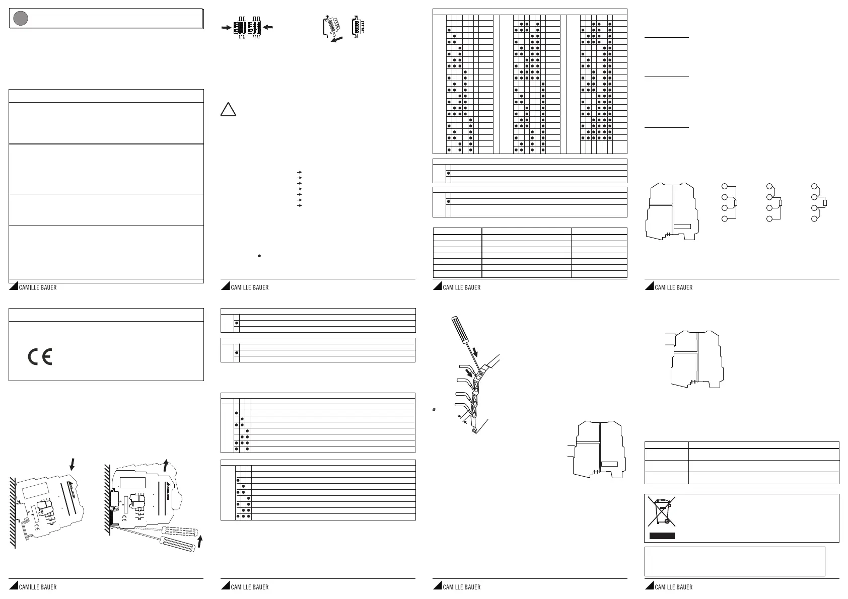
MESSBEREICH START
6SW178°C
0
-10
-20
-30
-40
-50
-100
-150
PT100 VERDRAHTUNG
1SW1
3 Draht
2 / 4 Draht
EINGANGSFILTER(*)
2SW1
Vorhanden
Abwesend
(*) Der Eingangsfilter verlangsamt dieAntwortzeit auf 200 ms und garantiert die
Rejektion des 50-Hz-Störungssignals, welches das Messsignal überlagert.
AUSGANGSSIGNAL
3SW145
0..20 mA
20..0 mA
4..20 mA
20..4 mA
0..10 Vdc
10..0 Vdc
0..5 Vdc
1..5 Vdc
MESSBEREICH OBERER WERT
11SW2SW21SW2222333444555666°C°C°C
0120340
5130350
10140360
15150370
20160380
25170390
30180400
35190410
40200420
45210430
50220440
55230450
60240480
65250500
70260520
75270550
80280580
85290600
90300620
95310650
100320
110330
(*) Siehe untereTabelle für die dazu gehörigen Werte.
AusgangsgrenzwertÜberbereich/ Fehlfunktion2,5 %±Fehlfunktion5 %±
20 mA20,5 mA21 mA
4 mA3,5 mA3 mA
0 mA0 mA0 mA
10 Vdc10,25 Vdc10,5 Vdc
5 Vdc5,125 Vdc5,25 Vdc
1 Vdc0,875 Vdc0,75 Vdc
0 Vdc0 Vdc0 Vdc
AUSGANGSSIGNALBEI FEHLFUNKTION
7SW2
Zum oberen Wert desAusgangssignalbereichs
Zum unteren Wert desAusgangssignalbereichs
BEREICHSÜBERSCHREITUNG(*)
8SW2
JA: eine 2.5%ige Bereichsüberschreitung ist akzeptabel; eine 5%ige
Bereichsüberschreitung wird als Fehlfunktion betrachtet
NEIN: die Fehlfunktion alleine verursacht einen 2.5%igen Überschreitungswert
Alle DIP-Schalter des Moduls befinden sich in der Position 0 als Standardkonfiguration.
Die Einstellungen entsprechen den folgenden Werten:
Obige Einstellungen sind also nur gültig, wenn alle DIP-Schalter auf 0 stehen. Wird
auch nur ein DIP-Schalter verändert, ist es erforderlich, alle anderen Parameter wie
folgt neu einzustellen.
Pt100
Eingangsfilter
Ausgangssignal
MessbereichAnfang
Maximaler Messbereich
Ausgangssignal bei Fehlfunktion
Bereichsüberschreitung
3-Draht
vorhanden
4..20 mA
0 °C
100 °C
In Richtung oberer Wert desAusgangssignals
JA: ein Wert von mehr als 2.5% ist akzeptierbar;
ein Wert von mehr als 5% wird als Fehlfunktion
interpretiert
EINSTELLUNG DER DIP-SCHALTER
Werkseinstellung
MERKE: Für alle nachfolgendenTabellen
DieAngabe von zeigt an, dass der DIP-Schalter in Position 1 steht (AN).
KeineAngabe bedeutet, dass der DIP-Schalter in der Position 0 steht (AUS).
15
6
7
8
2
3
4
POWER
SUPPLY
OUTPUT
INPUT
4-DrahtAnschluss
1
2
3
4
3-DrahtAnschluss
1
2
3
4
2-DrahtAnschluss
1
2
3
4
RTD transmitter (PT100)
with galvanic insulation
0
1
1
5
6
7
8
2
3
4
SW1
SW2
POWER
SUPPLY
OUTPUT
INPUT
19.2..30 Vdc
P< 500 mW
V / I
+
+
-
-
PT100 4/ 3 / 2 wires
Range : -150..650 °C
Load : R500/ R2 k
I meas. : < 900A
Test Voltage : 1.5 kV, 50 Hz, 1 min
Amb. Temp. : -20..+65 °C
<>
m
W
W
V
I
SINEAX VS40
RTDtransmitter(PT100)
withgalvanicinsulation
0
1
15
6
7
8
2
3
4
SW1SW2
POWER
SUPPLY
OUTPUT
INPUT
19.2..30 Vdc
P< 500 mW
V / I
+
+
-
-
PT100 4/ 3 / 2 wires
Range: -150..650°C
Load: R500/ R2k
I meas. : <900A
Test Voltage: 1.5kV, 50Hz, 1min
Amb. Temp. : -20..+65°C
<>
m
WW
VI
SINEAX VS40
EntsorgungvonaltenElektroundElektronikgeräten(gültiginderEuropäischenUnionundanderen
europäischenLändernmitseparatemSammelsystem)
DiesesSymbolaufdemProduktoderaufderVerpackungbedeutet,dassdiesesProduktnichtwieHausmuII
behandeltwerdendarf.StattdessensolldiesesProduktzudemgeeignetenEntsorgungspunktzumRecyclen
vonElektroundElektronikgerätengebrachtwerden.WirddasProduktkorrektentsorgt,helfenSiemit,
negativenUmwelteinflüssenundGesundheitsschädenvorzubeugen,diedurchunsachgemäßeEntsorgung
verursachtwerdenkönnten.DasRecyclingvonMaterialwirdunsereNaturressourcenerhalten.Fürnähere
InformationenüberdasRecyclendiesesProdukteskontaktierenSiebitteIhrlokalesBürgerbüro,Ihren
HausmüllAbholserviceoderdasGeschäft,indemSiediesesProduktgekaufthaben.
MI001830-F/D
Camille BauerAG
Aargauerstrasse 7
CH-5610 Wohlen/Switzerland
Phone +41 56 618 21 11
Fax +41 56 618 35 35
e-Mail: info@camillebauer.com
http://www.camillebauer.com
Produktspezifikationen
| Marke: | Camille Bauer |
| Kategorie: | Audio/Video-Konverter |
| Modell: | SINEAX VS40 |
Brauchst du Hilfe?
Wenn Sie Hilfe mit Camille Bauer SINEAX VS40 benötigen, stellen Sie unten eine Frage und andere Benutzer werden Ihnen antworten
Bedienungsanleitung Audio/Video-Konverter Camille Bauer

4 September 2025
3 September 2025
3 September 2025
3 September 2025
3 September 2025
Bedienungsanleitung Audio/Video-Konverter
Neueste Bedienungsanleitung für -Kategorien-
29 März 2026
29 März 2026
24 März 2026
22 März 2026
22 März 2026
21 März 2026
21 März 2026
15 März 2026
12 März 2026
6 März 2026