CRUX UC-1 Bedienungsanleitung
CRUX Nicht kategorisiert UC-1
Lies die bedienungsanleitung für CRUX UC-1 (4 Seiten) kostenlos online; sie gehört zur Kategorie Nicht kategorisiert. Dieses Handbuch wurde von 22 Personen als hilfreich bewertet und erhielt im Schnitt 4.3 Sterne aus 8 Bewertungen. Hast du eine Frage zu CRUX UC-1 oder möchtest du andere Nutzer dieses Produkts befragen? Stelle eine Frage
Seite 1/4
Adds reverse camera input in Uconnect systems.
Works on diesel powered trucks.
Plug and Play.
- Not compatible with vehicles with heated seats or steering wheel.
Uconnect 8.4” Screen with 52-Pin connector
Screen 6-button/2-knob with 52-Pin connector Uconnect 5”
-button/2-knob with 52-Pin connector Uconnect 4.3” Screen 6
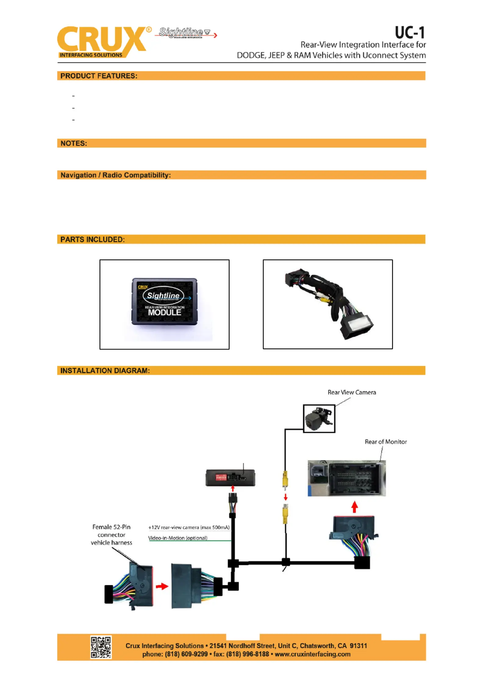
UC-1
Harness
UC-1 Interface Module
rev.031220
1/4
UC-1 Interface Module
UC-1 Harness
Produktspezifikationen
| Marke: | CRUX |
| Kategorie: | Nicht kategorisiert |
| Modell: | UC-1 |
Brauchst du Hilfe?
Wenn Sie Hilfe mit CRUX UC-1 benötigen, stellen Sie unten eine Frage und andere Benutzer werden Ihnen antworten
Bedienungsanleitung Nicht kategorisiert CRUX

17 Januar 2026
16 Januar 2026
14 Januar 2026
8 Oktober 2025
19 September 2025
14 September 2025
8 August 2025
8 August 2025
8 August 2025
8 August 2025
Bedienungsanleitung Nicht kategorisiert
Neueste Bedienungsanleitung für -Kategorien-
3 April 2026
3 April 2026
3 April 2026
3 April 2026
3 April 2026
3 April 2026
3 April 2026
3 April 2026
3 April 2026
3 April 2026