Hager WJC051B Bedienungsanleitung
Hager Nicht kategorisiert WJC051B
Lies die bedienungsanleitung für Hager WJC051B (2 Seiten) kostenlos online; sie gehört zur Kategorie Nicht kategorisiert. Dieses Handbuch wurde von 15 Personen als hilfreich bewertet und erhielt im Schnitt 4.1 Sterne aus 8 Bewertungen. Hast du eine Frage zu Hager WJC051B oder möchtest du andere Nutzer dieses Produkts befragen? Stelle eine Frage
Seite 1/2
6LE007524A
1
WJC051B ateha
Motion detector 3-wire 1.1 m
z
09/2020 - 6LE007524AHager Controls S.A.S., 33 rue Saint-Nicolas, B.P. 10140, 67703 SAVERNE CEDEX, France - www.hager.com
Safety instructions
Electrical equipment may only be installed and
assembled by a qualified electrician in ac-
cordance with the relevant installation stan-
dards, guidelines, regulations, directives, safe-
ty and accident prevention regulations of the
country.
Failure to comply with these installation inst-
ructions may result in damage to the device,
fire or other hazards.
These instructions are an integral component
of the product and must be retained by the end
user.
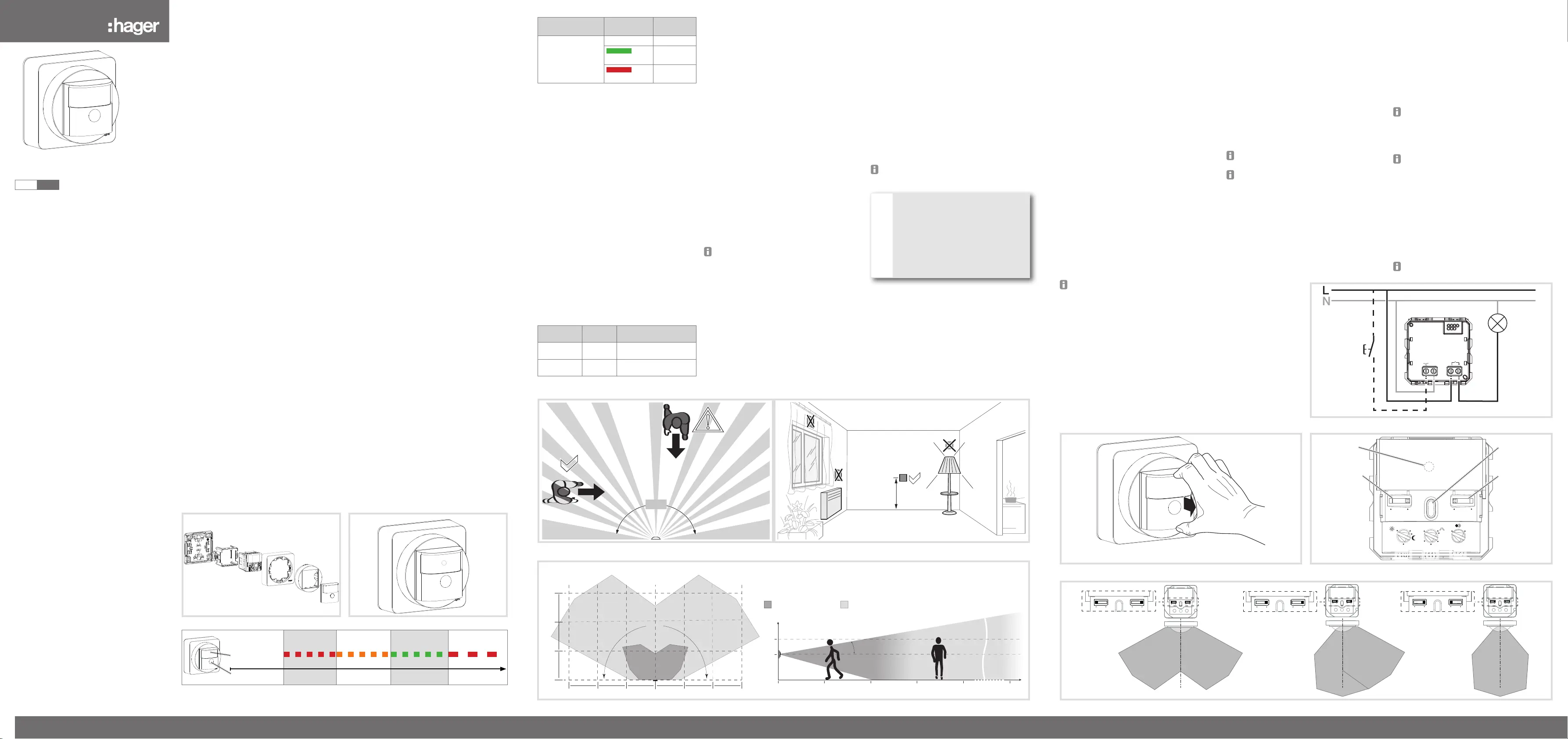
Design and layout of the device
(Figure 1)
(1) Mounting plate
(2) Mounting adapter
(3) Motion detectors
(4) Upper casing
(5) Mounting device cover
(6) Cover motion detector
Function
Correct use
-Automatic switching of lighting depending on
heat motion and ambient brightness
-manual switching via integrated button
-Only suitable for use in indoor areas with no
drip and no spray water.
-Assembly on the wall
Product characteristics
-integrated button for selecting operating modes
and special functions
-Lockable integrated button
-Operating mode Automatic, Semi-automatic can
be selected
-Display operating mode via LED
-Potentiometer for setting the response bright-
ness, delay time and detection sensitivity
-Additional adjustment of the response bright-
ness via Teach-In function
-Pulse encoder mode for current pulse/stairwell
circuits
-Adjustable detection angle for adaptation of the
detection area
-Party function
-Presence simulation
-optional extension unit operation via installation
button
-Expansion of detection area possible in the
case of WXF051 by means of stair motion de-
tector (master/slave configuration)
Operating modes
The motion detector detects heat motion caused
by people, animals, or objects.
Automatic mode
-The light will be switched on for the delay time,
if movements are detected in the detection area
and the set brightness threshold is undershot.
Each detected movement restarts the delay
time.
-The light will be switched off if no additional
movements are detected in the detection area
and the set delay time has elapsed.
Semiautomatic mode:
-The light is switched on manually for the delay
time via the button on the device or an extensi-
on unit button. Each detected movement or
each pressing of the button restarts the delay
time.
-The light will be switched off automatically if no
additional movements are detected in the de-
tection area and the set delay time has elapsed.
Operation
Operating concept (Figure 2)
(7) Button
(8) Status LED (behind lens)
Operation is executed by pushing the button (7) on
the motion detector:
-Keeping the button pressed activates special
functions. Selection of the special functions is
supported by the LED display (Figure 3).
Automatic mode
-A short press of the button switches the switch
mode. The switch mode is displayed via the
status LED behind the optics cover of the moti-
on detector.
Semiautomatic mode:
-A short press of the button switches the lighting
on.
Select switch mode via button (automatic
mode)
The operation button is not disabled (see Disab-
ling/enabling switch mode selection via button).
Briefly press the button (7) repeatedly until the
desired switch mode is selected. (Table 1)
The status LED (6) indicates the selected
switch mode.
Button operationLED displaySwitch
mode
Repeated short
press on button
–Automatic
green
Permanent
ON
red
Permanent
OFF
Table 1: Selection of switch mode and LED
display
Disabling/enabling switch mode selection via
button
The selection of the switch mode via the button
can be locked, e.g. for operation in public buil-
dings.
Keep the button pressed for more than 15
seconds, until the status LED is flashing green
(Figure 3).
Selection of the switch mode via the button is
disabled.
or if the button is locked:
Keep the button pressed for more than 15
seconds, until the status LED is flashing green
(Figure 3).
Selection of the switch mode via the button is
possible again.
Switch on lighting via push-button extension
unit (table 2)
Optionally the lighting can be switched on via
a mechanical push-button extension unit. For
extension unit operation, the lighting is switched on
independently of the set response brightness.
Lighting stateOperation
button
Performance of the insert
OFFShort
press
Load is switched on for the
set delay time
ONShort
press
Extension of switch-on
time by the set delay time
Table 2: Operation via push-button extension
unit
Activating/interrupting party function
The party function switches the lighting on for 2
hours.
Keep the button pressed for more than 5
seconds, until the status LED is flashing red
(Figure 3).
The lighting is switched on for 2 hours. During
this time the status LED is flashing red. Upon
elapse of 2 hours, the motion detector switches
to Automatic/Semi-automatic operation mode.
Briefly press the button or the extension unit.
The party function will be cancelled, the motion
detector returns to automatic/semi-automatic
operation mode.
Activating/deactivating presence simulation
During operation, the motion detector counts the
motion detections in one full hour and saves the
result. With active presence simulation at the be-
ginning of the hour with the most detections saved,
the light will be switched on for the duration of the
delay time, even no motion is detected.
During the presence simulation, presence detec-
tion and extension unit commands will continue to
be executed normally.
The presence simulation cannot be activated
via the extension unit.
Keep the button pressed for more than 20
seconds, until the status LED is slowly flashing
red (Figure 3).
The presence simulation is active. During this time
the status LED lights orange. The motion detector
switches the lighting on at the saved time.
To deactivate presence simulation:
While presence simulation is active, keep the
button pressed for more than 20 seconds, until
the status LED is slowly flashing red (Figure 3).
The presence simulation will be deactivated
and the orange status LED will go out. The
motion detector returns to the automatic/semi-
automatic operating mode.
Installation and electrical connection
Selecting installation location
-Note recommended installation height of 1.1 m.
-Observe the motion orientation: a distinction is
made between "direct approach" and "transver-
se motion". Motions transverse to the motion
detector can be detected better than motions
toward the motion detector (Figure 4, Figure 5).
-Select an installation location that is free of vibra-
tion. Vibrations can cause undesired switching.
-Avoid sources of interference in the detection
area (Figure 5). Sources of interference, e.g.
heating elements, ventilation systems, air con-
ditioners and lamps that are cooling down can
cause undesired switching (Figure 4).
To avoid disturbing influences, the detection
angle can be restricted (see Restriction of the
detection area).
DANGER!
Touching live parts can result in an
electric shock!
An electric shock can be lethal!
Disconnect the connecting cables
before working on the device and cover
all live parts in the area!
ç
Connecting and installing the device
Mount the mounting plate (1) correctly on a
suitable surface (fastening material not within
scope of delivery
Connect motion detector (3) according to the
connecting diagram (Figure 6)
Insert motion detector (3) into the mounting
adapter (2) and snap onto the mounting plate.
Attach upper casing (4) with mounting device
(5) and cover (6) on the motion detector (3).
z
Funktion
Party function
Teach-In
Keylock
Presence simu-
lation
LED display
Red
orangegreenred
Hold time
operation button
> 5 s>10 s> 15 s> 20 s
Fig. 3: Selection of the special functions and LED display
(1)
(2)
(3)
(4)
Figure 1: Design and layout of the device
(8)
(7)
Fig. 2: Operating and display elements
Commissioning
Basic settings
The basic settings for commissioning can be made
directly using the motion detector operating ele-
ments. The operating elements for commissioning
are located underneath the cover (6).
Removing cover
Remove cover by hand (Figure 7)
Overview of operation and adjustment
elements (Figure 8)
(7) Button
(8) Status LED
(9) Detection angle adjuster
(10) Response brightness potentiometer
(11) Delay time potentiometer
(12) Sensitivity potentiometer
Setting the detection area
The detection angle can be restricted for the right
side and for the left side via each adjuster (Figure
8, 9) between 45° ... 90° for each adjuster. This
can be carried out on the device. Thus the detec-
tion angle can be between 90° and 180° (Figure 9).
Use the adjusters to set the detection angle for
each side.
Further adjustments can be made to the
detection area by activating/deactivating the
motion sensors (see Setting the function of the
detection sensors).
Setting the detection performance
Test mode must be used to test the detection per-
formance. In test mode, the motion detector works
independent of brightness. Each detection swit-
ches the lighting and status LED on for 1 second.
Thereafter motion detection will be deactivated for
2 seconds.
The motion detector is connected and ready for
operation.
Set the response brightness potentiometer
(Figure 8, 10) to Test (T).
Leave the detection area and observe the swit-
ching behaviour.
If the motion detector switches on without moti-
on in the detection area, then sources of interfe-
rence are present (see Installation location).
Reduce the sensitivity if necessary and blank
out sources of interference by adjusting the
detection angle or removing them.
Check the detection area using a detection test
and adjust if necessary.
Test mode ends if no movement is detected for
3 minutes or a brightness value is set.
If the detection area of a motion detector is
too small, it can be extended in the case of
WXF051 by using stair motion detectors as
extension units.
Setting the response brightness
The response brightness is the brightness value
saved in the motion detector; when this value is
undershot the motion detector switches the con-
nected load if movements are detected. The res-
ponse brightness can be set between approx. 5 ()
over 150 Lux (factory setting) to daytime operation
(). The symbol stands for brightness-indepen-
dent switching. The response brightness can be
variably adjusted in the intermediate areas.
In order to control the lighting in stairwells in ac-
cordance with DIN EN12464-1, 2003-3, select
the 150 Lux potentiometer setting.
Turn the response brightness potentiometer
(Figure 8, 10) to the desired position.
To save the current ambient brightness as
response brightness, use the Teach-In function
(see Saving response brightness automatically
(Teach-In function)).
Saving response brightness automatically
(Teach-In function)
Keep the button (7) pressed for more than 10
seconds, until the orange status LED (8) is
flashing.
The motion detector detects the current ambient
brightness and saves it as response brightness.
The brightness saved via Teach-In is active until
a change occurs via the potentiometer.
ca. 180°
çç
1,10 m
Figure 4: Installation location of the motion detectors and motion orientation
10°
2
0
[m]
[m]
1.1
1.75
Detection area at:
"direct approach"
"transverse motion"
84
0
48
0
4
8
12
12
180°
468
12
12
Figure 5: Detection area of the motion detector with nominal installation height 1.1 m
Figure 7: Dismantling of cover
Lux
T
150
30
3
10s
10
1min
+-
...
90°
45°
...
45°
90°
(7)
(8)
(9)
(9)
150
(10)
(10)
(10)
(10)
(10)
(10)
(10)
(10)
(10)
(10)
(10)
(10)
(10)
3
(11)
(11)
(11)
(11)
(11)
(11)
(11)
(11)
(12)
(12)
(12)
(12)
(12)
(12)
(12)
(12)
(12)
(12)
(12)
(12)
Figure 8: Operation and adjustment elements
L
E
N
WJC051B
Figure 6: Connection of 3-wire motion detector
90° ... 45°45° ... 90°
90° ... 45°45° ... 90°
90° ... 45°45° ... 90°
90° ... 45°45° ... 90°
90° ... 45°45° ... 90°
90° ... 45°45° ... 90°
~ 180°
~ 135°
~ 90°
Figure 9: Setting the detection angle
(5)
(6)
Produktspezifikationen
| Marke: | Hager |
| Kategorie: | Nicht kategorisiert |
| Modell: | WJC051B |
Brauchst du Hilfe?
Wenn Sie Hilfe mit Hager WJC051B benötigen, stellen Sie unten eine Frage und andere Benutzer werden Ihnen antworten
Bedienungsanleitung Nicht kategorisiert Hager

27 September 2025
27 September 2025
26 September 2025
26 September 2025
26 September 2025
26 September 2025
26 September 2025
26 September 2025
26 September 2025
26 September 2025
Bedienungsanleitung Nicht kategorisiert
Neueste Bedienungsanleitung für -Kategorien-
28 Februar 2026
28 Februar 2026
28 Februar 2026
28 Februar 2026
28 Februar 2026
28 Februar 2026
28 Februar 2026
28 Februar 2026
28 Februar 2026
28 Februar 2026