Kichler Kenton 52815CPZ Bedienungsanleitung
Kichler Beleuchtung Kenton 52815CPZ
Lies die bedienungsanleitung für Kichler Kenton 52815CPZ (3 Seiten) kostenlos online; sie gehört zur Kategorie Beleuchtung. Dieses Handbuch wurde von 2 Personen als hilfreich bewertet und erhielt im Schnitt 4.9 Sterne aus 2 Bewertungen. Hast du eine Frage zu Kichler Kenton 52815CPZ oder möchtest du andere Nutzer dieses Produkts befragen? Stelle eine Frage
Seite 1/3
IS-52813-US
For warranty information please visit: kichler.com/warranty
We’re here to help 866-558-5706
Hrs: M-F 9am to 5pm EST
1) Find a suitable location on the wall to mount your xture. Location should be
within 7 feet of electrical outlet.
2) Remove mounting plate [A] from canopy [G] by unscrewing xture mounting
screws [B] (2 on top of canopy, 2 on bottom of canopy). Retain screws for re-
attaching mounting plate to canopy.
3) Place mounting plate [A] at against wall in desired location. Mounting plate
should be positioned with anges on top and bottom. Use mounting plate to mark
two (2) hole locations in keyhole slots:
4) Fixture can be mounted using drywall wing expansion bolts [I] or wood screws [J].
a) If a marked location on the wall coincides with the location of a wall stud or
other solid wood beam, drill a Ø3/32” [Ø2.3mm] hole at that location through
the mounting surface and into the stud or beam.
b) If a marked location on the wall coincides with drywall only, drill a Ø3/8”
[Ø9.5mm] hole at that location through the drywall.
5) Remove mounting plate from wall.
6) If either marked location on the wall has the larger Ø3/8” [Ø9.5mm] hole, take
note of the keyhole slot on the mounting plate that corresponds to that location on
the wall.
a) Remove a drywall wing expansion bolt [I] from parts bag and remove screw
from expansion bolt.
b) Pass screw through the mounting plate from the inside at the corresponding
keyhole slot.
c) Thread the expansion bolt back onto the screw as shown. Bolt should be
threaded onto screw far enough so the end of the screw barely protrudes
through other side of bolt.
d) Repeat using additional drywall wing expansion bolt in parts bag with 2
nd
keyhole slot in mounting plate if 2
nd
location on wall also has larger Ø3/8”
[Ø9.5mm] hole.
7) Place mounting plate [A] against wall in desired installation location.
a) If a drywall wing expansion bolt was installed in a keyhole slot, push the
expansion bolt anges into larger drilled hole(s) in wall as the mounting plate
is placed against wall.
b) If a smaller Ø3/32” [Ø2.3mm] hole was drilled at marked location on wall,
insert a wood screw [J] through corresponding keyhole slot and into drilled
hole in wall once mounting plate is at against wall.
8) Tighten screws in both keyhole slots against mounting plate. Once tightened,
loosen screws slightly to allow mounting plate to be removed from wall.
9) Loosen set screw at the bottom of decorative tube [H] and slide tube along the
pre-installed cord [F] and into hole on bottom of canopy [G]. Slip lock washer [K]
and hex nut [L] over threads on end of decorative tube inside canopy and tighten
hex nut until the decorative tube is secured to canopy. Tighten set screw at bottom
of decorative tube.
10) Remove mounting plate [A] from wall and re-attach to canopy [G] using xture
mounting screws [B]previously removed in step #2.
11) Hang xture on wall by aligning heads of screws in wall with larger holes of keyhole
slots and carefully passing mounting plate over screw heads. Slide xture down
slightly so threads of screws between wall and screw heads are seated at the top of
narrow portion of keyhole slot.
12) Insert recommended bulb(s).
13) Insert plug into 120-volt electrical outlet.
14) Turn the light on/o by using the switch on the cord.
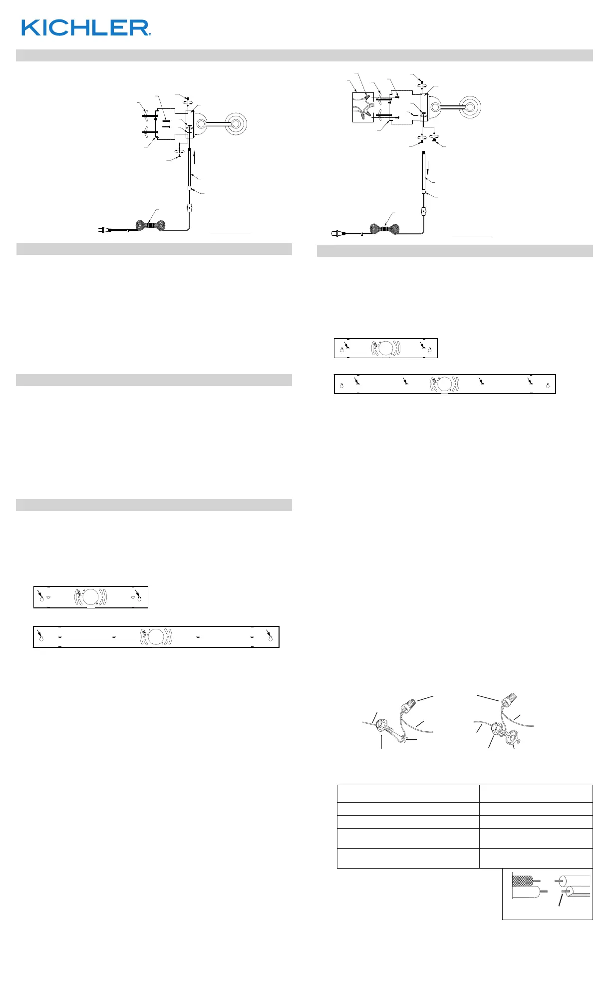
FIXTURE DIAGRAM
PARTS LIST
CAUTIONS
CAUTION – RISK OF SHOCK –
Disconnect Power at the main circuit breaker panel or main fusebox before starting
and during the installation.
WARNING:
This xture is intended for installation in accordance with the National Electrical Code
(NEC) and all local code specications. If you are not familiar with code requirements,
installation by a certied electrician is recommended.
CLEANING:
●Always be certain that electric current is turned o before cleaning.
●Only a soft damp cloth should be used. Harsh cleaning products may damage the
nish.
[A] Mounting Plate
[B] Fixture Mounting Screw (Qty. 4)
[C] Outlet Box (not supplied)
[D] Plate Mounting Screw (Qty. 2)
[E] Wire Hole Cover
[F] Cord With Switch
[G] Canopy
[H] Decorative Tube (on supplied cord)
[I] Drywall Wing Expansion Bolt With Screw
(Qty. 4 - model numbers 52813/52814, Qty. 6 - model numbers 52815/52816)
[J] Wood Screw
(Qty. 4 - model numbers 52813/52814, Qty. 6 - model numbers 52815/52816)
[K] Lock Washer (on cord inside canopy)
[L] Hex Nut (on cord inside canopy)
[M] Wire Nuts (Qty. 3)
Mounting With Cord (without electrical box - VIEW “A”)
Mounting without Cord (directly to electrical box - VIEW “B”)
VIEW "A"
VIEW "B"
F
F
H
E
E
B
B
A
I
B
L
K
J
A
C
M
I
D
B
L
K
SET SCREW
H
G
SET SCREW
REV 19-DEC-2025
1) Remove mounting plate [A] from canopy [G] by unscrewing xture mounting screws
[B] (2 on top of canopy, 2 on bottom of canopy). Retain screws for re-attaching
mounting plate to canopy.
2) Attach mounting plate [A] to outlet box [C] using the plate mounting screws [D] in
the holes that align with the holes in outlet box. Mounting plate should be positioned
with anges on top and bottom.
3) For model numbers 52813/52814, mark two (2) hole locations in the center of outer
oval slots on mounting plate. For model numbers 52815/52816, mark four (4) hole
locations in the center of outer oval slots on mounting plate.
4) Remove mounting plate from outlet box and retain plate mounting screws.
5) Drill a Ø3/8” [Ø9.5mm] hole at each marked location on wall.
NOTE: If any marked location on the wall coincides with the location of a
wall stud or other solid wood beam, a wood screw should be used instead
of a drywall expansion bolt. In this case, drill a Ø3/32” [Ø2.3mm] hole at that
location instead of the Ø3/8” [Ø9.5mm] hole.
6) Remove drywall wing expansion bolts [I] from bag and remove screws from
expansion bolts. Pass each screw through the outer oval slots of mounting plate
from the inside. Thread each expansion bolt back onto each screw as shown.
Bolts should be threaded onto screws far enough so the ends of the screws barely
protrude through other side of bolts.
NOTE: If a smaller Ø3/32” [Ø2.3mm] hole was drilled in the wall as instructed
in step #5, do not insert expansion bolt through corresponding slot in
mounting plate for that location.
7) Place the mounting plate against the wall, pushing the drywall wing expansion bolt
anges into the larger drilled hole(s) in wall as the mounting plate is placed against
wall. For locations on a wall stud or other solid wood beam, insert wood screw [J]
through corresponding slot in mounting plate and into drilled hole in wall.
8) Re-attach mounting plate [A] to outlet box [C] using plate mounting screws [D]
previously removed in step #4.
9) Tighten all screws until mounting plate is secure.
10) Loosen the set screw in the bottom of the decorative tube [H] and push the cord
[F] up into the canopy to expose more length of the cord inside the canopy. Cut the
cord above the canopy, leaving at least 6 inches of cord from the back center of the
canopy.
11) Remove the hex nut [L] and lock washer [K] from the cord.
12) Remove decorative tube and cord from xture.
13) Insert the wire hole cover [E] into hole in the bottom of the canopy [G]. Screw hex
nut [L] (previously removed from cord) onto threads of hole cover inside canopy to
secure cover in-place.
14) Split the end of the cord (still connected to xture) 3 inches and strip the wire ends
.5 inches.
15) Grounding instructions: (See Illus. a or b).
a) On xtures where mounting strap is provided with a hole and two raised
dimples, wrap ground wire from outlet box around green ground screw, and
thread into hole.
b) On xtures where a cupped washer is provided, attach ground wire from
outlet box under cupped washer and green ground screw, and thread into
mounting strap.
If xture is provided with ground wire, connect xture ground wire to outlet box
ground wire with wire connector after following the above steps. Never connect
ground wire to black or white power supply wires.
16) Make wire connections. Reference chart below for correct connections and wire
accordingly.
Connect Black or Red Supply Wire to:Connect White Supply Wire to:
BlackWhite
*Parallel cord (round & smooth)*Parallel cord (square & ridged)
Clear, Brown, Gold or Black without
Tracer
Clear, Brown, Gold or Black with
Tracer
Insulated wire (other than green) with
copper conductor
Insulated wire (other than green)
with silver conductor
*Note: When parallel wire (SPT 1 & SPT 2) are
used. The neutral wire is square shaped or ridged
and the other wire will be round in shape or
smooth (See illus.)
Neutral Wire
17) Push xture to wall, carefully passing canopy [G] over the mounting plate.
NOTE: Make sure wires do not get pinched between mounting plate and
canopy or between canopy and wall.
18) Secure xture into place using the four xture mounting screws [B] previously
removed in step #1: two on top and two on bottom.
19) Insert recommended bulb(s).
GREEN GROUND
SCREW
CUPPED
WASHER
OUTLETBOX
GROUND
FIXTURE
GROUND
DIMPLES
WIRE CONNECTOR
OUTLETBOX
GROUND
GREEN GROUND
SCREW
FIXTURE
GROUND
b
MODEL #52813 & #52814
MODEL #52815 & #52816
MODEL #52813 & #52814
MODEL #52815 & #52816
Produktspezifikationen
| Marke: | Kichler |
| Kategorie: | Beleuchtung |
| Modell: | Kenton 52815CPZ |
Brauchst du Hilfe?
Wenn Sie Hilfe mit Kichler Kenton 52815CPZ benötigen, stellen Sie unten eine Frage und andere Benutzer werden Ihnen antworten
Bedienungsanleitung Beleuchtung Kichler

18 März 2026
18 März 2026
11 März 2026
24 Februar 2026
23 Februar 2026
16 Februar 2026
15 Februar 2026
14 Februar 2026
14 Februar 2026
6 Februar 2026
Bedienungsanleitung Beleuchtung
Neueste Bedienungsanleitung für -Kategorien-
18 März 2026
18 März 2026
18 März 2026
18 März 2026
18 März 2026
18 März 2026
18 März 2026
18 März 2026
18 März 2026
18 März 2026